background image

10

ADJUSTMENTS

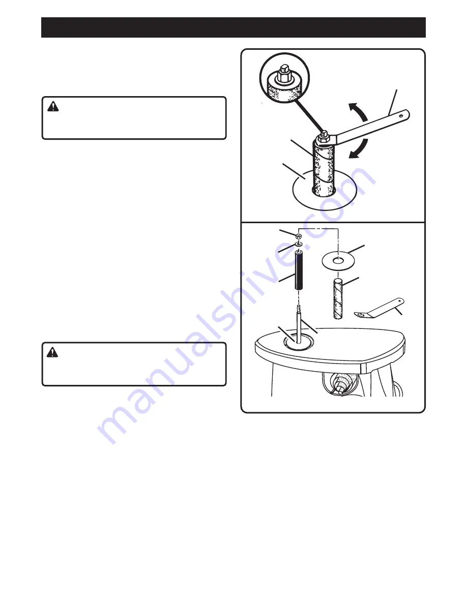
REMOVING SANDING SLEEVES

See Figure 3.

Follow these directions to remove sanding sleeves.

Unplug the sander.

WARNING:

Failure to unplug the tool could result in accidental
starting causing serious injury.

Grasp and hold the sanding sleeve on the spindle.

Loosen the hex nut using the wrench provided.

NOTE:

 If the hex nut is too tight and the spindle shaft

spins inside the sanding sleeve, grasp the flats on
top of the spindle shaft with a 1/4 in. wrench (not
provided) and loosen the hex nut.

Remove the hex nut, upper spindle washer, sanding
sleeve, rubber spindle, and throat plate.

NOTE:

  It is recommended that you clean dust

accumulations from the throat plate, throat plate nest,
and under the lower spindle washer after each use.
Remove the lower spindle washer and clean dust
accumulations.

INSTALLING SANDING SLEEVES

(All except 1/2 in. (12.7 mm))

See Figure 4.

Follow these directions to install sanding sleeves.

Unplug the sander.

WARNING:

Failure to unplug the tool could result in accidental
starting causing serious injury.

Place the lower spindle washer over the spindle, fin
side down.

NOTE:

  Always install the fin side of the washer

down. The fins help push dust through the dust
exhaust port opening, preventing buildup of dust.
Dust in this area may cause the oscillating motion to
stop. Always use the lower spindle washer with all
sanding sleeves.

Select and install the correct throat plate. Refer to
SELECTING THROAT PLATES/UPPER SPINDLE
WASHERS earlier in this manual.

Select and install the correct rubber spindle.

Install the appropriate sanding sleeve on the rubber
spindle.

NOTE:

  If the sanding sleeve becomes difficult to

remove or install, apply talcum powder on the rubber
spindle or inside the sanding sleeve before installing
the sanding sleeve on the rubber spindle.

Install the upper spindle washer and hex nut.

NOTE:

 Use the 7/8 in. (22.2 mm) washer for the 3/4

in. (19.1 mm), 1 in. (25.4 mm), and 1-1/2 in.
(38.1 mm) rubber spindles. Use the 1-13/16 in.
(46 mm) washer for the 2 in. (50.8 mm) and 3 in.
(76.2 mm) rubber spindles.

Grasp and hold the sanding sleeve on the spindle.

Tighten the hex nut using the wrench provided.

NOTE:

 Tighten the hex nut only enough to expand

the rubber spindle against the inner wall of the
sanding sleeve. 

Do not overtighten

.

Return the wrench to the storage area.

Fig. 3

Fig. 4

SANDING

SLEEVE

THROAT

PLATE

WRENCH

TO LOOSEN

TO TIGHTEN

HEX NUT

UPPER

SPINDLE

WASHER

RUBBER

SPINDLE

THROAT

PLATE

SANDING

SLEEVE

WRENCH

LOWER

SPINDLE

WASHER

SPINDLE

Summary of Contents for OSS500

Page 1: ...tor safety Properly cared for it will give you years of rugged trouble free performance WARNING To reduce the risk of injury the user must read and understand the operator s manual Thank you for buyin...

Page 2: ...ses with side shields and a full face shield when needed We recommend Wide Vision Safety Mask for use over eyeglasses or standard safety glasses with side shields Always wear eye protection which is m...

Page 3: ...ed service technician at an autho rized service center Stay constantly aware of cord location and keep it well away from the moving parts of the tool USE OUTDOOR EXTENSION CORDS When tool is used outd...

Page 4: ...WET SANDING Failure to comply can result in electrical shock causing serious injury DO NOT OPERATE THIS TOOL WHILE UNDER THE INFLUENCE OF DRUGS ALCOHOL OR ANY MEDICATION STAY ALERT AND EXERCISE CONTR...

Page 5: ...ctions vital to the operation or maintenance of the equipment SAVE THESE INSTRUCTIONS DOUBLE INSULATION Double insulation is a concept in safety in electric power tools which eliminates the need for t...

Page 6: ...the packing materials from around the tool Lift the tool carefully from the box and place it on a level work surface NOTE The sander is heavy Ask for assistance if necessary Do not discard the packin...

Page 7: ...m tall however you can only sand material up to 3 11 16 in 93 7 mm thick The 1 2 in 12 7 mm sanding sleeve fits directly on the 1 2 in 12 7 mm spindle and requires no rubber spindle It is secured in p...

Page 8: ...nd could result in a hazardous condition leading to possible serious personal injury SPINDLE HEX NUT SANDING SLEEVE 1 in 25 4 mm THROAT PLATE TABLE TOP THROAT PLATE STORAGE AREA WRENCH STORAGE AREA SW...

Page 9: ...face is uniform NOTE Do not use the sander without a sanding sleeve Doing so will damage the rubber spindle Select and install the desired sanding sleeve for your particular application As mentioned p...

Page 10: ...washer down The fins help push dust through the dust exhaust port opening preventing buildup of dust Dust in this area may cause the oscillating motion to stop Always use the lower spindle washer with...

Page 11: ...The fins help push dust through the dust exhaust port opening preventing buildup of dust Dust in this area may cause the oscillating motion to stop Always use the lower spindle washer with all sanding...

Page 12: ...face Place the sander back on the work surface aligning the holes in the base with the holes in the work surface NOTE If the sander does not appear to be stable make sure the rubber stabilizers are in...

Page 13: ...control of the workpiece COLLECTING DUST See Figure 10 A dust exhaust port is provided to help keep dust to a minimum It is located under the table top on the back of the sander The end of a standard...

Page 14: ...r are subject to accelerated wear and possible premature failure as the fiberglass chips and grindings are highly abrasive to bearings brushes commutators etc Consequently we do not recommend that thi...

Page 15: ...15 NOTES...

Page 16: ...VE THE FOLLOWING INFORMATION MODEL NUMBER SERIAL NUMBER OSS500 EXTENSION CORD CAUTION When using a power tool at a considerable distance from a power source be sure to use an extension cord that has t...

Reviews: