background image

11

English

FEATURES

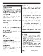
KNOW YOUR GENERATOR

See Figure 3.

The safe use of this product requires an understanding of 

the information on the product and in this operator’s manual 

as well as a knowledge of the project you are attempting. 

Before use of this product, familiarise yourself with all 

 operating features and safety rules.

AC CIRCUIT BREAKER

The circuit breaker is provided to protect the generator 

against electrical overload and can be used to turn the 

generator’s electrical power on or off.

AIR FILTER

The air filter helps to limit the amount of dirt and dust drawn 

into the unit during operation.  

CHOKE LEVER

The choke lever is used when starting the engine. 

ENGINE SWITCH

The engine switch is used in combination with the recoil 

starter grip to start the generator. It is also used to turn 

the generator off.

FUEL LEVEL GAUGE

Consult the fuel level gauge to determine the amount of 

fuel remaining in the generator.

FUEL TANK

6 litres

FUEL VALVE

The flow of fuel through the generator is controlled by the 

position of the fuel valve.

COMMON (GROUND) TERMINAL

The ground terminal is used to assist in properly grounding 

the generator to help protect against electrical shock. 

Consult with a local electrician for grounding requirements 

in your area.

OIL DRAINAGE PLUG

See Figure 10

When changing the engine oil, the oil drainage plug is 

loosened to allow old oil to be drained.

OIL CAP/DIPSTICK

Remove the oil fill cap to check and add oil to the generator 

when necessary.

RECEPTACLES

Your generator has the following single phase, 50 Hz outlets: 

one 230 Volt AC, 15 Amp receptacle. These can be used 

for operating appropriate appliances, electrical lighting, 

tools, and motor loads.

RECOIL STARTER GRIP

The recoil starter grip is used (along with the engine switch) 

to start the generator’s engine.

DC TERMINALS

The DC terminals may ONLY be used for charging 12 volt 

automotive type batteries.
The terminals are coloured red to identify the positive (+) 

terminal and black to identify the negative (-) terminal. The 

battery must be connected to the generator DC terminals 

with the proper polarity ( battery positive to generator red 

terminal and battery negative to the generator black terminal).

DC CIRCUIT PROTECTOR 

The DC circuit protector automatically shuts off the DC 

battery charging circuit when the DC charging circuit is 

overloaded, when there is a problem with the battery, or 

when the connections between the battery and the generator 

are improper.

BREATHING VALVE

Regulate the internal pressure of the fuel tank and keep 

the fuel running on lines.

ASSEMBLY

UNPACKING

This product has been shipped completely assembled.

n

  Remove one end of the box and carefully slide out the 

generator and any accessories. 


NOTE: 

The generator is heavy. If you must lift the unit 

out of the box, get another person to help you and lift 

with your legs, not your back.

n

  Inspect the unit carefully to make sure no damage 

occurred during shipping.

n

  Do not discard the packing material until you have 

 carefully inspected and satisfactorily operated the 

 product.

n

   If any parts are damaged or missing, please contact 

your nearest authorised service centre for assistance.

PACKING LIST

Generator 

Spark Plug Wrench

Oil Bottle /  Oil Funnel 

Operator’s Manual

Summary of Contents for RGN1200A

Page 1: ...E GENERATOR SET OPERATOR S MANUAL RGN1200A Important It is essential that you read the instructions in this manual before assembling maintaining and operating this machine Subject to technical modific...

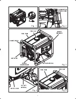
Page 2: ...Fig 4 Fig 5 Fig 3 OIL CAP DIPSTICK RECOIL STARTER GRIP AIR FILTER CHOKE LEVER FUEL CAP CIRCUIT BREAKER FUEL TANK FUEL CAP OIL CAP DIPSTICK OIL FILL HOLE CARBURETOR DRAIN SCREW OIL CAP DIPSTICK Fig 2 F...

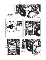
Page 3: ...2 Fig 6 ON OFF ON OFF Fig 8 Fig 7 AIR FILTER RECOIL STARTER GRIP FUEL VALVE Fig 9 CHOKE LEVER TO START CHOKE CLOSED TO RUN CHOKE OPEN LATCHES CHOKE LEVER TO START CHOKE CLOSED LATCHES...

Page 4: ...3 21 2 Fig 10 ON OFF Fig 11 Fig 12 Fig 13 ON OFF ON OFF SPARK PLUG CAP SPARK PLUG FUEL LINE FUEL VALVE BARB FUEL VALVE O RING FILTER SEDIMENT CUP OIL DRAINAGE PLUG...

Page 5: ...or receptacles n Do not use the generator with electrical cords which are worn frayed bare or otherwise damaged n Before storing allow the engine to cool n Do not operate the generator in rain snow or...

Page 6: ...diately after use they are HOT and will cause burn injury n Do not connect to a building s electrical system unless a transfer switch has been properly installed by a qualified electrician n Do not al...

Page 7: ...d to observe safe practices can result in electric shock Running the generator gives off carbon monoxide an odourless colourless poison gas Breathing carbon monoxide can cause nausea fainting or death...

Page 8: ...ormed only by a qualified service technician For service contact your nearest AUTHORISED SERVICE CENTRE for repair When servicing use only identical replacement parts WARNING Observe all normal safety...

Page 9: ...The unit is equipped with an oil sensor which will automatically shut off the engine if oil level falls below a safe limit HOT SURFACE WARNING Do not touch the muffler or aluminium cylinder of the eng...

Page 10: ...scribed later in this manual 2 Plug in and turn on the first load preferably the largest load highest wattage you have 3 Permit the generator output to stabilise engine runs smoothly and attached devi...

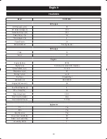
Page 11: ...Engine Number UP154 Engine Type 4 Stroke air cooled OHV Gasoline Bore x Stroke mm 54 x 38 Displacement cc 87 Starting System recoil Fuel Type Unleaded fuel Lubrication oil SAE 10W 30 Engine Oil Volum...

Page 12: ...orhasthefollowingsinglephase 50Hzoutlets one 230 Volt AC 15 Amp receptacle These can be used for operating appropriate appliances electrical lighting tools and motor loads RECOIL STARTER GRIP The reco...

Page 13: ...l injury APPLICATIONS This generator is designed to supply electrical power for operating compatible electrical lighting appliances tools and motor loads BEFORE OPERATING THE UNIT Position the generat...

Page 14: ...enerator n Start the engine refer to STARTING THE ENGINE section NOTE Do not start the vehicle while the battery charging cable is connected and the generator is running The vehicle or the generator m...

Page 15: ...lowing the instructions in the Checking Adding Oil section n Reinstall the oil cap dipstick NOTE Used oil should be disposed of at an approved disposal site See your local oil retailer for more inform...

Page 16: ...fuel being drained from the tank n Open fuel valve n When the fuel has drained from the tank close the fuel valve and reinstall fuel line on barb DRAINING THE CARBURETOR See Figure 2 n Turn the engine...

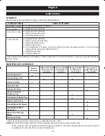
Page 17: ...torage life For recommendations contact your nearest authorised service center MAINTENANCE SCHEDULE Before each use After 1st month or 20 hours of operation Every 3 months or 50 hours of operation Eve...

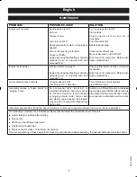
Page 18: ...cuit breaker is OFF Item plugged in is defective Turn ON the AC circuit breaker Try a different item Generator makes a spark knock or pinging noise An occasional light knocking or pinging underheavylo...

Page 19: ...18 English WIRING DIAGRAM RGN1200A...

Page 20: ...Techtronic Industries Australia Pty Ltd Level 1 660 Doncaster Road Doncaster VIC 3108 Australia Techtronic Industries New Zealand Ltd 18 26 Amelia Earhart Avenue Mangere Auckland 2022 New Zealand...

Reviews: