background image

4

 Original 

instructions


| English


CAUTION

Without safety alert symbol
Indicates a situation that may result in property damage.

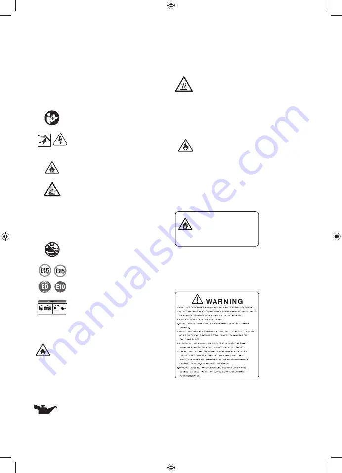
SAFETY LABELS

The information below can be found on the generator. For 
your safety, please study and understand all of the labels 
before starting the generator.
If any of the labels come off the product or become hard to 
read, contact an authorised service centre for replacement.

You will be killed or seriously hurt if you 
do not follow the operator’s manual 
instructions.


The generator is a potential source 
of electric shock. Do not expose to 
moisture, rain, or snow. Do not operate 
with wet hands or feet.

Risk of Fire. Do not add fuel while the 
product is operating.

Exhaust contains poisonous carbon 
monoxide gas that can cause 
unconsciousness or death. Operate 
in well-ventilated, outdoor areas away 
from open windows or doors.
Using a generator indoors can kill 
you in minutes. Generator exhaust 
contains carbon monoxide. This is a 
poison you cannot see or smell.

Do not expose to rain or use in damp 
locations.


Do not use E15 or E85 fuel (or fuel 
containing greater than 10% ethanol) 
in the product.

Never use inside a home or garage, 
even if doors and windows are open.
Only use outside and far away from 
windows, doors, and vents.

FUEL WARNING

1RVPRNLQJZKHQ¿OOLQJZLWKXQOHDGHGIXHO'RQRWRYHU¿OO

Full level is 25 mm below the top of the fuel neck. Stop the 

HQJLQHIRU¿YHPLQXWHVEHIRUHUHIXHOOLQJWRDYRLGWKHKHDW
IURPWKHPXIÀHULJQLWLQJIXHOYDSRXUV

ENGINE LUBRICANT WARNING

<RX PXVW DGG RLO EHIRUH ¿UVW RSHUDWLQJ WKH JHQHUDWRU

Always check the oil level before each operation. The oil 

level should always register within the hatched area on the 
dipstick. The product is equipped with an oil sensor which 
will automatically shut off the engine if oil level falls below 
a safe limit. 

HOT SURFACE WARNING

'R QRW WRXFK WKH PXIÀHU RU DOXPLQLXP F\OLQGHU RI WKH

engine. They are very HOT and will cause severe burns. 

'RQ¶W SXW DQ\ ÀDPPDEOH RU FRPEXVWLEOH PDWHULDOV LQ WKH

direct path of the exhaust.

CLEARANCE WARNING

While operating and storing, keep at least 1 m of clearance 
on all sides of the product, including overhead. Allow a 
minimum of 30 minutes of “cool down” time before storage. 

+HDW FUHDWHG E\ PXIÀHU DQG H[KDXVW JDVHV FRXOG EH KRW

enough to cause serious burns and/or ignite combustible 
objects.

RISK OF FIRE AND SERIOUS BURNS

Risk of fire and serious burns:

Never remove fuel cap when unit is running .

Shut off engine and allow the unit to cool at the least five minutes.

Remove cap slowly.Use fuel stabilizer for storage.

Never remove fuel cap when the product is running.
Shut off engine and allow the product to cool down for at 

OHDVW¿YHPLQXWHV

Remove the cap slowly. Use fuel stabilizer for storage.

WARNING LABEL

1.  Read the operator’s manual and all labels before 

operating.

2.  Do not operate in a confined area where exhaust gases, 

smoke or fumes could reach dangerous concentrations.

3.  Check for spilt fuel or fuel leaks.
4.  Do not refuel while engine is running for petrol driven 

engines.

5.  Do not operate in a hazardous location, e.g. where 

Summary of Contents for RGN3600B

Page 1: ...ORIGINAL INSTRUCTIONS Low Power Generating Set RGN3600B...

Page 2: ...Important It is essential that you read the instructions in this manual before assembling operating and maintaining the product Subject to technical modification...

Page 3: ...8 Fuel cap 9 Fuel tank 10 Oil fill hole 11 Oil cap dipstick removed 12 Fuel valve 13 Fuel valve on 14 Fuel valve off 15 Choke lever 16 To start choke closed 17 To run choke open 18 Screw 19 Spark plu...

Page 4: ...Fig 4 Fig 5 Fig 6 11 8 9 6 10 Fig 7 Fig 8 16 15 13 12 17 14...

Page 5: ...Fig 9 7 13 12 14 Fig 10 2 Fig 11 20 19 18 21 Fig 12...

Page 6: ...Fig 13 Fig 15 Fig 16 Fig 17 Fig 14 22 28 26 27 29 24 25 23 30...

Page 7: ...240V AC 240V ON OFF OIL ALERT LAMP 9 1 2 3 4 8 7 6 5 Fig 18 CONTROL PANEL LABEL See figure 18 1 Multimeter 2 Circuit breaker 3 AC receptacle 4 AC receptacle 5 PE Terminal 6 Oil alert lamp 7 Engine sw...

Page 8: ...generator and the transfer switch have been properly installed and the electrical output has been verified by a qualified electrician The connection must isolate the generator power from utility powe...

Page 9: ...rom all types of combustible material Do not touch the muffler or cylinder during or immediately after use they are hot and will cause burn injury Do not connect to a building s electrical system unle...

Page 10: ...ds and as necessary a full face shield when operating this product Failure to use in dry conditions and to observe safe practices can result in electric shock Running the generator gives off carbon mo...

Page 11: ...KHDW IURP WKH PXI HU LJQLWLQJ IXHO YDSRXUV ENGINE LUBRICANT WARNING RX PXVW DGG RLO EHIRUH UVW RSHUDWLQJ WKH JHQHUDWRU Always check the oil level before each operation The oil level should always reg...

Page 12: ...tput of the generator Motor Size HP Running Watts Watts required to start motor Universal Capacitor Split phase 1 8 275 N A 850 1200 1 6 275 600 850 2050 1 4 400 800 1050 2400 1 3 450 950 1350 2700 1...

Page 13: ...s to sequentially add loads as follows 1 With nothing connected to the generator start the engine as described later in this manual 2 Plug in and turn on the first load preferably the largest load hig...

Page 14: ...one end of the box and carefully slide out the generator and any accessories NOTE The generator is heavy If you must lift the product out of the box get another person to help you and lift with your l...

Page 15: ...nt or 2 stroke engine lubricants will damage the engine and should not be used Unscrew the oil cap dipstick and remove Wipe dipstick clean and re seat in hole do not re thread Remove dipstick again an...

Page 16: ...ency situation Put the engine switch in the OFF O position WARNING While operating and storing keep at least 1 m of clearance on all sides of the product including overhead Allow a minimum of 30 minut...

Page 17: ...n serious burns SPARK PLUG MAINTENANCE See figure 11 The spark plug must be properly gapped and free of deposits in order to ensure proper engine operation To check Remove the spark plug cap Clean any...

Page 18: ...e Half Load 13 86 hrs Approvals AS NZS 3010 Yes Euro Emission Yes EMC Yes Uncertainty dB 2 19 Noise level 4 m LpA dB A 70 81 Noise level 7 m LpA dB A 74 Noise level LwA dB A 93 TRANSPORTING Turn engin...

Page 19: ...OFF Turn ON the AC circuit breaker Item plugged in is defective Try a different item Generator makes a spark knock or pinging noise An occasional light knocking or pinging under heavy load is not a ca...

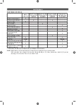
Page 20: ...adjust idle speed Check adjust valve clearance 1 OHDQ IXHO WDQN DQG OWHU 1 Check fuel hose XHO OWHU Inspect Replace Check all hose connections Inspect fuel tank vapor vent if equipped Inspect carbon c...

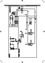
Page 21: ...WIRING DIAGRAM...

Page 22: ......

Page 23: ......

Page 24: ...ted by Techtronic Industries Australia Pty Ltd 31 Gilby Road Mount Waverley VIC 3149 Melbourne Australia Techtronic Industries N Z Limited 2 Landing Drive Mangere Auckland 2022 New Zealand 09997917700...

Reviews: