background image

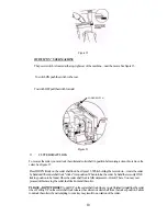
Install the BOTTOM key blank in the left vise jaw—flip down the machines full-function key gauges and 
carefully top shoulder gauge the left key to the key in the right-hand vise jaw. 

Carefully release the carriage and align the left-hand key blanks "V" cut with the machines stylus—the "V" 
cut in the key blank in the right-hand vise jaw should "fall" into place around the "V" profile of the cutter 
wheel. 

Use your hand to carefully turn the cutter wheel BACKWARDS to verity that the cutter wheels teeth do 
not touch the "V" cut in the key blank. 

Verify that the stylus is completely seated in the "V" cut in the left-hand key blank. If it is and the cutter 
wheel will not turn Backwards by hand or the cutter wheel teeth "tick" the "V" cut in the right-hand key 
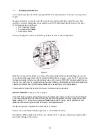
blank—then spacing needs to be adjusted. See figure 17. 

Figure 17 

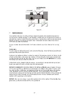
Loosen the #10-32 screw securing the cutter shaft assembly in place using your 5/32" Alien hex wrench— 
retighten the screw with LIGHT pressure. You want just enough retightening pressure on the screw to 
keep the cutter shaft assembly in place so you can't move it with your hand—but you can move it with 
gentle to moderate tapping with your small plastic mallet. See figure 18. 

Turn the cutter BACKWARDS with your hand to observe which way you must move the cutter. Use your 
small plastic mallet to "nudge" the cutter shaft assembly in the direction you want to go. It is a good idea to 
verify the cutter position in the "V" cut in the key after every "tap" of the small plastic mallet. Verify your 
results by turning the cutter Backwards with your hand. Also verify that the stylus is properly seated in the 
"V" cut in the left-hand key. Adjust the position of the carriage as required to keep the stylus seated in the 
"V" cut in the key. 

Continue with this procedure until you are satisfied with the position of the cutter. Once you are satisfied 
you may wish to turn ON your key machine and observe the spinning cutter wheel in the "V" cut in the key. 
This test must only be done AFTER you have turned the cutter Backwards by hand and verify that no 
cutter wheel teeth will contact either side of the "V" cut. With the machine running you may want to 
lightly "nudge" the spinning cutter a little more before retightening the #10-32 screw. 

SWITCH OFF THE KEY MACHINE.


Retighten the #10-32 Screw.


14

Summary of Contents for RY45

Page 1: ...E PRICES MAY VARY FROM YOUR DISTRIBUTOR Model RY45 OPERATOR S MANUAL Rytan Model RY45 Semi Automatic Key Duplicating Machine for Cylinder Keys and Automotive Keys Rytan Products Are Designed and Manuf...

Page 2: ...n Made Rytan Inc Model RY45 universal key duplicating machine Your new key machine has been designedand built with heavy duty components designed for the most demanding shop and van use As you become...

Page 3: ...d Never yank cord to disconnect from receptacle Keep cord from heat oil and sharp edges Never remove the ground connection from the plug If you use a two wire adapter be sure to properly connect the g...

Page 4: ...configuration The top jaw can be shimmed with 040 drill rod included to make deeper cuts in small keys Narrow groove style top and bottom vise jaws are possible by reversing the entire carriage B Key...

Page 5: ...wear Some steel keys will ruin your cutter wheel with just one pass NOTE Some automotive presentation keys are made of Hardened Steel and can ruin the cutter wheel instantly Don t befooled by the deco...

Page 6: ...Y KEY IS CLAMPED ON 102 OF ITS BLADE STANDARD JAW WILL CLAMP MAXIMUM AMOUNT OF KEY KEY IS CLAMPED ON 142 OF Its BLADE FIGURE2 TOP VISE JAW REPLACEMENT Either top vise jaw may be replaced at any time y...

Page 7: ...ee figure 4 REVERSING THE CARRIAGE The carriage is reversed on your RY45 key machine to switch from standard vise jaw configuration to narrow groove key clamping configuration To reverse the carriage...

Page 8: ...st the key into the vise jaw gently slide the key left and right a few times about 1 8 will do to seat the key into the vise jaws With the bottom shoulder of the standard cylinder key about 1 32 away...

Page 9: ...centered in the vise jaws Ignition key ridge will contact the face of the TOP vise jaw See figure 10 Door and truck key ridge will contact the face of the BOTTOM vise jaw See figure 9 See figure 9 for...

Page 10: ...12 Position the key in the vise so that the tip edge of the key is about 1 32 or less from the right edge of the vise jaws Operate the full function key gauges by rotating the key gauge shaft toward...

Page 11: ...the cutter by hand until the cutter shaft lock clicks intoposition When turningthe cutter by hand there is only ONE locking position to befound Once the cuttershaft lock isfullydepressed Holdit There...

Page 12: ...nut TheLeft HandNutisselflockingasyouuseit Over tighteningthecutterwheelnutmaymakeithardertoremovelaterandmayresultindamagingthecuttershaft lockorcuttershaftpulley PLEASE DON TFORGETtopullUPonthecutte...

Page 13: ...ey to compress the stylus all the way back Hold the carriage in this position during the adjustment process Observe that the cutter wheel misses the key blank in the right vise by carefully turning th...

Page 14: ...aws DO NOT bottom shoulder the keys into the vise there may be a small radius in the corner of the key blank s blade and bottom shoulder area Clamping in this area may ANGLE the key blank in the vise...

Page 15: ...y in place so you can t move it with your hand but you can move it with gentle to moderate tapping with your small plastic mallet See figure 18 Turn the cutter BACKWARDS with your hand to observe whic...

Page 16: ...carriagetotheLEFTmakingawidecutslightly morethanVi wide Seefigure19 PullthecarriagebackandswitchOFFthekeymachine Removethetwokey blanksfromtheright handvisejaw ReinstallonekeyblankintheRightvisejaw us...

Page 17: ...ching theface of the closed visejaw Gently turn theslotted screw stud withyour screwdrivertothe left as viewed fromthe frontof the machineandstopwhenyoufeelthestudcontactthekey machine scarriage remem...

Page 18: ...parts dry the next day with a clean rag or soft paper towel WARNING Do not turn the machipe over and set it on the Power Switch Lubricate the vise jaw plungers inside the carriage remove the key clam...

Page 19: ...y machine the qualityof the operator orthe qualityof the adjustments made to the machine All the questionsremainunanswered There is enly one way toget good results on aconsistentbasis Buy a quality bu...

Page 20: ...One key cuts fine and the next doesn t This time it may be the key gauges Sometimes key machine operators don t flip back the full function key gauges all the way and the left hand key gauge CRASHES i...

Page 21: ...rface when the cutter has sharp pointed teeth The ridges will get smoother as the cutter wears until finally you have to buy a new cutter or get the old cutter resharpened When you put on the new or r...

Page 22: ...continue to surface from time to time Best thing to do is a Never cut a key that s brought in by your customer Cut only what you know and make sure it always comes from YOUR inventory b Place a small...

Page 23: ...s HOW DO I REPLACE The Stylus Loosen the red T turn knob on the top of the stylus holder Pull out the stylus and replace with a new one Pushhard againstthetip of the stylusto compress the stylusspring...

Page 24: ...service for the RY45 key duplicating machine 21 WARRANTY The warranty registration form must be filled out and mailed to Rytan Inc within TEN days of date of purchase Failure to do so will VOID the w...

Page 25: ...AIRED BY UNAUTHORIZED SOURCES OR HAVE BEEN SUBJECT TO NEGLECT ABUSE MISUSE OR ACCIDENT INCLUDING SHIPPING DAMAGES OR MACHINES WHO S WARRANTY REGISTRATION FORMS HAVE NOT BEEN MAILED TO RYTAN INC WITHIN...

Page 26: ...r Foot 35 RY9058 Cap Screw 36 RY9024 Bronze Oilite Bearing 41 RY9055 Hex Jam Nut 42 RY9041 Switch 44 RY10035 Cutter Shaft Lock 48 RY42 Ball Bearing Cutter Shaft Assy 50 RY82 3 Piece Thrust Bearing Ass...

Reviews: