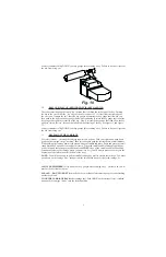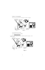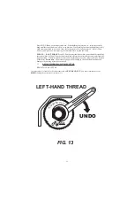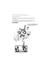
Reinstall the stick-shift and drive shaft assembly and reattach the two piece drive shaft linkage and
youre almost done.
Turn the machine back onto its feet and observe the carriage spring attached to the ¼ diameter
grooved pin driven into the carriage shaft. Take your small hammer and a steel rod or drift and drive
the pin back into the carriage shaft. Stop when the bottom edge of the carriage spring almost touches
the carriage shaft.
Test the operation of the carriage and the feel of the carriage spring. If the carriage spring seems
a bit to strong drive the grooved spring pin retaining pin in a little bit further. If the carriage seems
a bit too weak - drive the grooved spring retaining pin up (from the bottom of the machine) a little
bit further. Test the carriage again.
The Carriage Shaft and Bronze Oilite® Bearings
Refer to the first part of The Carriage Spring to disconnect the linkages and remove the stick-shift
lever assembly and the carriage spring. Remove the linkages form the carriage shaft using a 1/8
Allen Hex Wrench to remove the shoulder bolt.
Drive the ¼ diameter carriage shaft pin used to retain the carriage and the carriage pin.
Look down onto the carriage shaft from the top of the carriage and lightly file the ¼ diameter hole
where the grooved pin was - the knurled section of the pin probably raised up small burrs on the
edge of the hole which might damage the carriage when the shaft is pulled out of the carriage. Also
turn the carriage shaft and expose the milled notch in the carriage shaft where the carriage release
mechanism locked the carriage back. The constant locking back and unlocking of the carriage
probably raised up a burr on the shaft at the edge of the milled notch remove any burr you may find
in this area with your file before trying to remove the carriage shaft.
Pull out the Carriage Shaft.
Use a piece of 1 diameter hard wood dowel purchased from your local hardware store. Cut off a
piece about 6 long and use it to pound out the bearings with a hammer.
Cut off a piece of 1 diameter hard wood dowel about 1 foot long and trim one end to ¾ diameter
about ½ long - to fit onto the new bronze Oilite® bearing.
From the right side of the machine push the 1 hardwood dowel through the 1 diameter bearing hole
go almost all the way through to the left side of the machine where the first bearing will be installed.
Slip the new bronze Oilite® bearing onto the modified end of the dowel and position the bearing
onto the 1 diameter hole. Notice the dowel pin going through the first hole and the bearing sitting
at the entrance of the 1 diameter hole act on their behalf for their own alignment. Use your hammer
to pound on the end of the dowel and drive the bronze Oilite® bearing into its hole. Remove the
dowel and insert the new carriage shaft leave the end of the carriage shaft extended about ½ out
of the right-side bearing hole and place your second bearing onto this shaft. Notice that the carriage
shaft now acts as an alignment guide for the second bearing. Use your 6 piece of 1 diameter
hardwood dowel and your hammer to pound in this bronze Oilite ® bearing.
Test to see if the new carriage shaft slides between the two bearings. If you were careful and pounded
them in straight you should be able to continue with the rest of the reassembly right away. If the
carriage shaft is just a little stiff you can probably leave it alone and let it work itself in over time.
If the carriage shaft seems to be tight then use a medium size plastic mallet and tap on the shaft in
all directions accessible to settle in the bearings. Stop when the carriage shaft gets just loose enough
to use.
Reassemble in the reverse order and refer to section in this manual titled HOW DO I REPLACE. .
The Carriage Spring and complete your assembly.
You should recheck the depth, depth overtravel and space adjustments on your machine and readjust
as necessary.
WHY DID WE DO IT THAT WAY . . .
23

