7
INSTALLATION—SPREADER ASSEMBLY
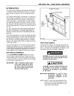
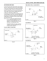
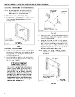
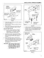
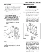
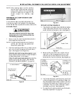
Figure 15
3.
Check that the side columns are plumb and square
with the floor and wall.
4.
Tighten all anchor hardware securing both side col-
umns to the wall.
5.
Remove any bar clamps that may have been used
to temporarily hold the side columns to the wall.
Door with Hood Assembly
NOTE: DO NOT change the location of the drive
motor without first contacting your Rytec
representative or the Rytec Customer
Support Department at 800-628-1909.
1.
Identify the drive motor side column by the wire
access holes along its outside edge. This is impor-
tant for the proper installation of the spreader
assembly.
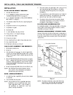
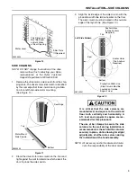
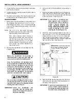
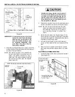
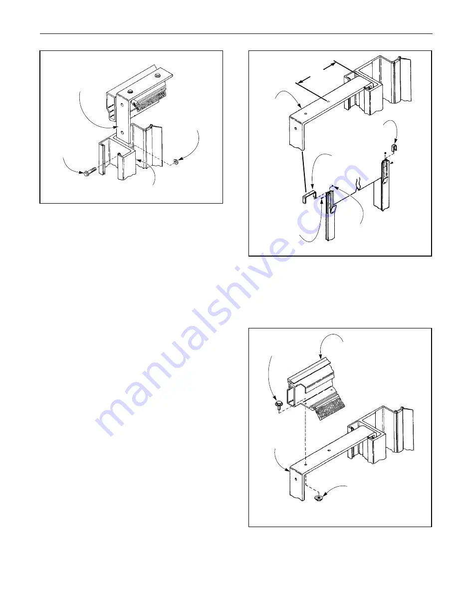
2.
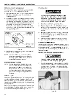
Attach a spreader assembly U-bracket on the
outside face of each side column using two
³₈
-16 x
1
¹₄
-in. serrated-flange hex screws and nuts for each
bracket. The U-brackets and mounting hardware
were shipped in the small parts carton.
(See Figure 16.)
IMPORTANT:
Attach the large U-bracket to the
drive motor side column with the
screw hole located
6
³₄
in. from
the end of the bracket, nearest to
the outside face of the side col-
umn. (See
Figure 16
.)
Figure 16
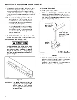
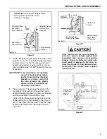
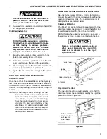
3.
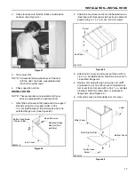
Attach the spreader assembly to the U-brackets
using two
³₈
-16 x 1
¹₄
-in. serrated-flange hex screws
and nuts at each end of the assembly. Face the
spreader so the brush is toward the front of the
door. (See Figure 17.)
Figure 17
A8500005
L-Bracket
(Fits Behind
Inside Face of
Serrated-Flange
Hex Screw (Two
on Each End)
Inside Face of
Serrated-Flange
Hex Nut (Two
on Each End)
Side Column)
Side Column
A8500152
6
³₄
in.
Serrated-Flange
Hex Nut (Two
Each Side)
Large
Large U-Bracket
(Drive Motor
Serrated-Flange
Hex Screw (Two
Each Side)
Small
U-Bracket
U-Bracket
Side Column)
A8500153
Header
Serrated-Flange
Hex Screw (Two
Each Side)
Serrated-Flange
Hex Nut
(Two per Side)
Support
Bracket
Extrusion
Left Side Column
Summary of Contents for Pharma-Roll
Page 1: ...Pharma Roll Installation Manual Revision January 15 2009 0715009 Rytec Corporation 2007...
Page 2: ......
Page 23: ...NOTES 19...
Page 24: ......

