8
INSTALLATION—HEAD ASSEMBLY
4.
Check that the side columns are plumb and square
with the floor and wall.
5.
Tighten all anchor hardware securing both side col-
umns to the wall.
6.
Remove any bar clamps that may have been used
to temporarily hold the side columns to the wall.
HEAD ASSEMBLY
1.
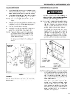
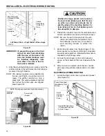
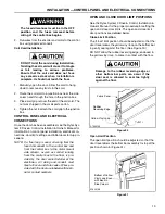
Before removing the head/fabric roll assembly from
the shipping crate, locate four
¹₂
-13 x 1
¹₄
-in. ser-
rated-flange hex screws, four
¹₂
-13 serrated-flange
nuts, and the flange bearing assembly in the small
parts carton.
NOTE:
The
¹₂
-13 x 6-in. hex screws that were
installed earlier will be used to attach the
head assembly to the side columns.
Also, some oversized doors require a
steel spacer between both side columns
and the head assembly. If your door is
oversized, locate two 9-in. x 1
³₄
-in. steel
spacers shipped in the small parts carton.
(The spacers are further identified by a
hole at each end.)
2.
Remove the head/fabric roll assembly from the
shipping crate.
Before the head/fabric roll assembly is
lifted into place, make sure both side col-
umns are secured to the building wall.
Also, the head/fabric roll assembly must
be secured to the forklift before lifting it in
place. Failure to properly secure the side
columns or the head/fabric assembly can
result in serious personal injury and prop-
erty damage. DO NOT remove the forklift
from under the head/fabric roll assembly
until it is secured to both side columns.
Use care when handling the fabric roll to
ensure that the fabric is not torn or dam-
aged. DO NOT remove the shipping bands
holding the fabric to the roll.
IMPORTANT: Install the head/fabric roll
assembly with the bottom bar/
fabric roll coming off the back of
the drum assembly.
3.
Using a forklift, lift the head/fabric roll assembly in
place.
4.
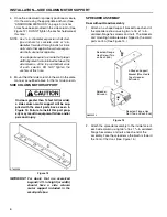
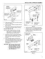
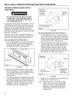
Position the head assembly in front of the pair of
holes near the top of each side column. Align the
holes in the motor mounting bracket with the holes
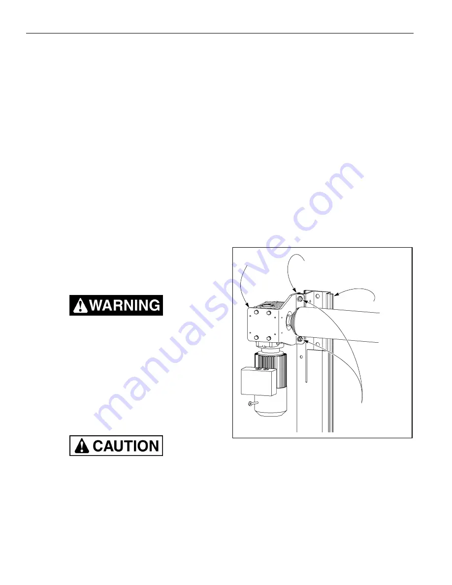
in the side column. (See Figure 18.)
IMPORTANT: If your door is oversized, two
large spacers were included in
the small parts carton. Failure to
install a spacer between the
motor mounting bracket and
flange bearing assembly could
result in damage to the door.
(See
Figure 18
and
Figure 19
.)
5.
Attach the motor mounting bracket to the side col-
umn using two
¹₂
-13 x 1
¹₄
-in. serrated-flange hex
screws and nuts (or two
¹₂
-13 x 2-in. screws and
nuts if spacers are required, or nuts only if 6-in.
screws were installed earlier). DO NOT tighten the
hex nuts at this time. (See Figure 18.)
Figure 18
6.
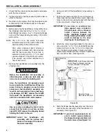
Slide the flange bearing assembly over the drum
shaft at the non-drive end of the head/fabric roll
assembly. (See Figure 19.)
IMPORTANT: If your door requires spacers, be
sure to install a spacer between
the flange bearing assembly and
the side column. (See
Figure 19
.)
A7500247
Serrated-Flange
Hex Screws and Nuts
IMPORTANT:
Install Spacer between
Motor Mounting Bracket and Side
Column (If Spacer Is Supplied)
Motor Mounting
Bracket
Side Column
Summary of Contents for Pharma-Roll
Page 1: ...Pharma Roll Installation Manual Revision January 15 2009 0715009 Rytec Corporation 2007...
Page 2: ......
Page 23: ...NOTES 19...
Page 24: ......

