7
Header
Extrusion
INSTALLATION—HEAD ASSEMBLY
5. Remove any bar clamps that may have been used
to temporarily hold the side columns (or pullouts) to
the wall.
Door with Hood Assembly
NOTE: DO NOT change the location of the drive
motor without first contacting your Rytec
representative or the Rytec Technical
Support Department at 800-628-1909.
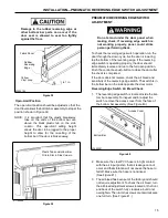
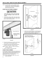
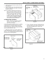
3. Attach the spreader assembly to the U-brackets
using two 3/8-16 x 1 1/4-in. serrated-flange hex
screws and nuts at each end of the assembly.
Face the spreader so the brush is toward the front
of the door. (See Figure 17.)
Serrated-Flange
Hex Screw
(Two Each Side)
1. Identify the drive motor side column by the wire
access holes along its outside edge. This is
important for the proper installation of the spreader
assembly.
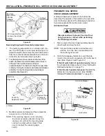
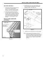
2. Attach a spreader assembly U-bracket on the
outside face of each side column using two
3/8-16 x 1 1/4-in. serrated-flange hex screws and
nuts for each bracket. The U-brackets and
mounting hardware were shipped in the small parts
carton. (See Figure 16.)
IMPORTANT:
Attach the large U-bracket to the drive
motor side column with the
screw hole
located 6-3/4 in. from
the end of the
bracket, nearest to
the outside face of
the side column. (See Figure 16.)
Support
Bracket
A8500153
Serrated-Flange
Hex Nut
(Two Each Side)
Left Side Column
Large
U-Bracket
6-3/4 in.
Small
U-Bracket
Large U-Bracket
(Drive Motor
Side Column)
Figure 17
4. Check that the side columns are plumb and square
with the floor and wall.
5. Tighten all anchor hardware securing both side
columns (or pullouts) to the wall.
6. Remove any bar clamps that may have been used
to temporarily hold the side columns (or pullouts) to
the wall.
HEAD ASSEMBLY
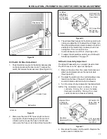
1. Before removing the head/fabric roll assembly from
the shipping crate, locate four
¹/₂
-13 x 1
¹/₄
-in. serrated-
flange hex screws, four
¹/₂
-13 serrated-flange nuts,
and the flange bearing assembly in the small parts
carton.
NOTE: On a door configured with pullouts, the
Serrated-Flange
Hex Screw (Two
Each Side)
A8500152
Serrated-Flange
Hex Nut (Two
Each Side)
Figure 16
four 1 1/4-in. long serrated-flange hex
screws
mentioned above in step 1 were
not shipped
with the door. Instead, the longer 1/2-13 x 6-in.
hex screws that were
installed earlier will be
used to attach the head assembly to the side
columns.


