3
PLANNED MAINTENANCE—DAILY INSPECTION
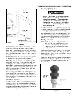
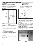
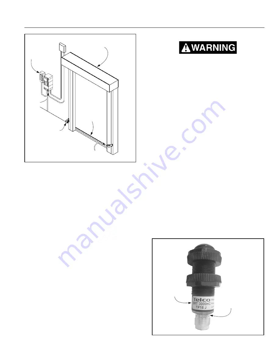
Fused
Disconnect
Rytec
Control
Panel
Left Side Column
(Photo Eye on
Front and Back Sides)
Head
Assembly
Bottom Bar
Assembly
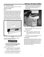
Reversing Edge Inspection
Do not stand under the door panel while
testing the door reversing function. If the
reversing edge switch is not working prop-
erly, the panel could strike the person per-
forming the test. Also, do not continue to
use the door if the reversing edge is not
operating properly.
While the door is running through the down cycle, tap
the bottom of the reversing edge. If the reversing edge
is operating properly, the door will immediately reverse
and run to the fully open position. Push the control panel
down key to close the door after the inspection is com-
plete. If the reversing edge is not working properly, see
“PNEUMATIC REVERSING EDGE SWITCH ADJUST-
MENT” on page 12 for the adjustment procedures.
A8500206
Right Side Column
(Photo Eye on Front and Back Sides)
Figure 3
Photo Eye Inspection
NOTE: Photo eyes act as a safety device to pre-
vent the door from closing if an object or
person is within either photo eye beam.
Head Assembly:
Inspect for dents or damage that may
prevent the door from opening or closing properly.
Door Panel:
Inspect panel for holes, tears, and worn
areas. If equipped with windows, inspect them for dam-
age or dirt that may impair vision — clean or replace as
required.
Side Columns and Covers:
Inspect for damage that
may prevent the door from operating properly.
Photo Eyes:
Inspect the lens of each photo eye for
damage or dirt that may prevent the photo eyes from
working properly — clean or replace as required.
Bottom Bar:
Inspect the bottom bar for damaged, miss-
ing, or loose hardware. Inspect the yellow vinyl seal
along the lower edge of the bottom bar for tears and
holes. Inspect the edge itself.
Counterweights and Straps:
Counterweights must be
properly adjusted. Counterweight straps must be in
good working condition, securely attached to the coun-
terweights and the drum assembly, and tracking prop-
erly on all rollers.
Check Door Operation
Run the door through four or five complete cycles to ver-
ify that the door is operating smoothly and efficiently,
and that binding or unusual noises do not exist. DO NOT
continue to operate the door if it is not running properly,
as this could compound the damage.
The photo eyes are not meant to be used
as door activators.
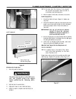
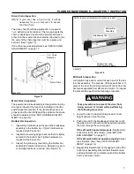
With power on, the green light indicates the photo eye
module is powered up. When the yellow light on the
receiver module is also lit, the emitter and receiver mod-
ules are properly aligned.
Placing your hand in front of the receiver breaks the light
path and causes the yellow light to go out. Removing
your hand causes the yellow light to come back on.
(See Figure 4)
Transmitter
Module
Designation
Power Light
(Green)
A2500258
Figure 4


