7
PLANNED MAINTENANCE—QUARTERLY INSPECTION
Drive Chain Inspection
NOTE: If your door has a hood cover, it will be
necessary for you to remove it to access
the drive chain.
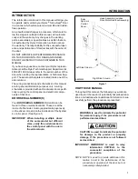
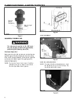
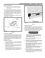
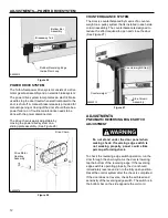
The drive chain should be adjusted for a maximum
¹/
₄
-in. deflection at its midpoint. The two sprockets the
chain is stretched across must be parallel with each
other. And the master link and retainer clip used to join
the ends of the chain together must be in place and
secured. (See Figure 15)
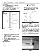
If the chain requires adjustment, see “DRIVE CHAIN
ADJUSTMENT” on page 17.
NOTE: Ensure all hardware is in place and tight.
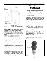
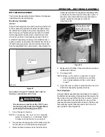
Bottom Bar
Assembly
Breakaway Tab
¹/
₄
-in. Chain
Deflection
A8500212
Yellow Vinyl Loop
With Reversing Edge
A8500079
Drive Chain
Figure 16
Kill Switch Inspection
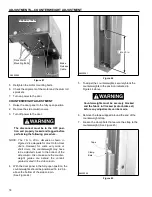
A kill switch has been mounted at each end of the bot-
tom bar assembly. The purpose of these switches is to
prevent the door from being operated if the bottom bar
becomes separated from either side column. To inspect
the kill switches, perform the following procedure.
Figure 15
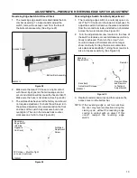
Motor Brake Inspection
The power drive brake assembly is designed to stop the
door panel travel at the locations indicated in the limit
switch inspection section. If the limit switches are set
properly and the door drifts past the set limits, the brake
should be adjusted. (See “MOTOR BRAKE ADJUST-
MENT” on page 16)
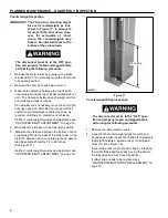
Bottom Bar Inspection
1. Inspect the hardware used to secure the breakaway
assembly to the bottom bar. Tighten hardware as
required. (See Figure 16)
2. Inspect the reversing edge to ensure that it is tightly
secured to the bottom bar. Tighten hardware as
required. (See Figure 16)
3. Inspect the yellow vinyl seal along the bottom bar
assembly for tears and abrasion. Replace any worn
or damaged parts as required. (See Figure 16)
Take precautions to prevent the door from
being opened or closed while performing
the following procedure.
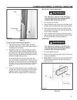
1. Lower the door to approximately head or chest
height and then stop the door.
2. Push one end of the breakaway bottom bar out of
the side column. It should not be possible to operate
the door through the control panel.
If the kill switch operated properly:
Reattach the
bottom bar to the side column. (See “BOTTOM
BAR ASSEMBLY” on page 11)
If the kill switch did not operate properly:
Adjust
the kill switch. (See “KILL SWITCH ADJUST-
MENT” on page 14)
3. Repeat the kill switch test on the opposite end of the
bottom bar assembly. After all the kill switch tests
and adjustments are complete, reattach the bottom
bar to each side column.

