10
OPERATION—CONTROL PANEL
4.
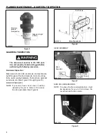
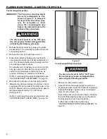
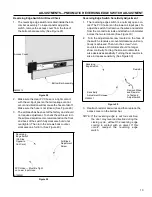
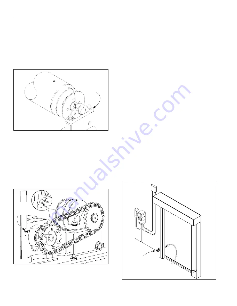
Pillow Block Bearings:
The drum roll is
supported by a pillow block bearing located at
each end of the drum roll. Each pillow block has a
lubrication fitting. (See Figure 20)
The bearings should be lubricated quarterly using
a lithium-based grease conforming to NLGI grade
2 standard. It should be a medium-viscosity, low-
torque rated grease, with an approved operating
temperature range of –30°F to 200°F.
Drum Roll
Grease Fitting
OPERATION
CONTROL PANEL
The Turbo-Seal door is equipped with the Rytec
System 4 Drive & Control, a solid-state, micro-proces-
sor-based control system designed exclusively to oper-
ate Rytec high-performance doors. It provides
connections for multiple activators, close-delay timers,
and status indicators. All command functions to operate
the drive and control system are software controlled.
For information on control panel operation see the Rytec
System 4 Drive & Control Installation & Owner’s Manual.
PHOTO EYES
A8500154
Figure 20
Pillow
Block
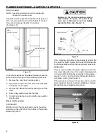
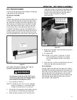
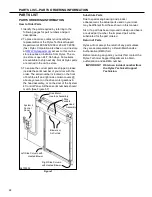
Doors are equipped with two sets of photo eyes to moni-
tor the front and back sides of the door. Each set of photo
eyes consist of an emitter (transmitter) photo eye and a
receiver photo eye. (See Figure 22)
The purpose of the photo eyes is to hold the door open
or, if the door is closing, reverse the direction of the door
if a person or object crosses the path of either photo eye
beam. After the obstruction breaking the photo eye
beam is removed:
• If the door was originally opened by an automatic
5.
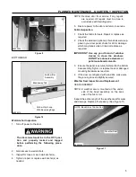
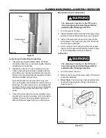
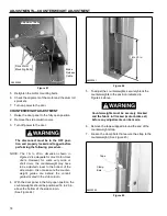
Drive Motor Gearbox Assembly
:
The oil level in
the gearbox should be checked regularly. The oil
level is checked at the plug located on the gearbox.
(See Figure 21)
Recommended oil for refilling the gearbox is SHC
630 synthetic gear oil. The gearbox is full when a
small amount of oil runs out of the lower plug hole.
Replace the O-ring on the refill plug as needed to
maintain a tight seal.
activator, the door will close automatically.
• If the door was originally opened by a non-auto-
matic activator, the door will remain open until it is
closed by the non-automatic activator.
NOTE: The safety photo eyes are not intended to
be used as door activators and will not
open the door when it is closed.
Remove Plug
to Check Level
Remove
Breather
to Add Oil
A8500081
Figure 21
Front
Photo Eye
Rear Photo Eye
(Not Shown)
6. Install the hood and side covers (if used).
7. Turn on power to the door.
A8500206
Figure 22


