14
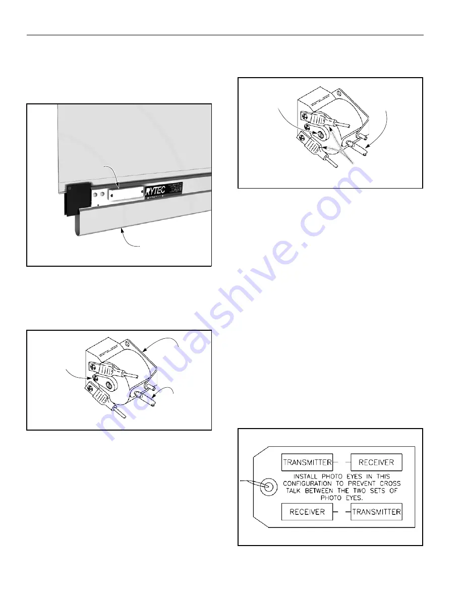
ADJUSTMENTS—KILL SWITCH ADJUSTMENT
KILL SWITCH ADJUSTMENT
Air Bleed Adjustment
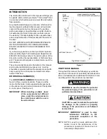
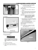
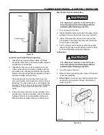
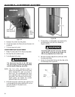
1. The kill switch is mounted near the coil cord end of the
the bottom bar assembly. To access the switch, first
remove the access cover. (See Figure 31)
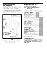
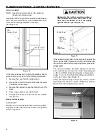
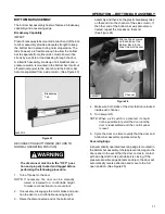
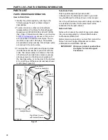
1. Remove the wires from the contact terminals and
attach an ohmmeter across the two terminals.
(See Figure 33)
Sensitivity
Adjustment
Screw
Upper Air
Input Post
Access Cover
A7500202
Remove Wires
to Test and
Adjust Switch
A8500212
Figure 31
Bottom Bar Assembly
Figure 33
2. To adjust the switch, turn the small adjusting screw,
located on the face of the switch, clockwise or coun-
terclockwise until continuity is achieved. Then turn
the screw two turns clockwise for final adjustment.
Adjusting the screw clockwise decreases sensitiv-
ity, counterclockwise increases sensitivity.
(See Figure 33)
3. Reattach the wires and replace the access cover.
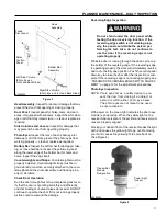
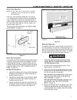
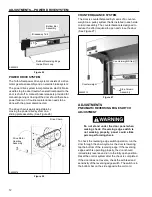
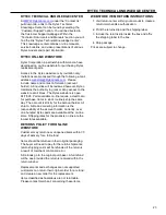
2. Make sure the clear PVC hose is tight on the air
input post so that air leakage cannot occur and
vibration will not cause the hose to fall off. Also
make sure the hose is not kinked. (See Figure 32)
Air Bleed
Adjustment
NOTE: If the kill switch is set too sensitive, it may
cause the door to stop during the opening
or closing cycle. If this occurs, readjust the
kill switch sensitivity setting.
PHOTO EYE ADJUSTMENT
Screw (One
on Each Side
of Switch)
A7500202
Kill Switch
PVC Hose Must
Be Tight on
Air Input Post
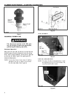
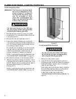
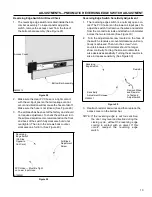
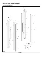
The door is equipped with two sets of photo eyes that mon-
itor the front and back sides of the door. Each set of eyes
consists of an emitter module and a receiver module.
To prevent one set of photo eyes from interfering with
the other set of eyes, the emitters and receivers are
mounted diagonally across from each other — the side
columns each have an emitter module and a receiver
module, from each set of eyes. (See Figure 34)
Figure 32
3. The air bleed has been set at the factory and should
not require adjustment. If adjustment is necessary,
turn the air bleed adjustment screws located on the
front and back of the switch fully clockwise — but do
not overtighten. Then turn each screw back (coun-
terclockwise) one full turn. (See Figure 32)
Sensitivity Adjustment
NOTE: The kill switch assembly is a normally
closed contact. The PVC hose is on the
upper air input post.
A7700046
Figure 34


