16
ADJUSTMENTS—MOTOR BRAKE ADJUSTMENT
Troubleshooting
If any of the green lights are not lit, check to make sure
that power is turned on and that all wiring has continuity
and is installed and connected correctly. If the green
lights are on but the yellow light is off, check the align-
ment of the emitter and receiver modules and clean
each eye using window cleaner and a soft, clean cloth.
1. Turn on the power to the door.
2. Move the door to the half-open position.
Take precautions to prevent the door from
being operated as you perform the follow-
ing procedure. Also, be cautious around
the moving parts exposed in the side col-
umns.
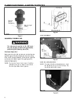
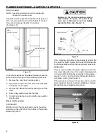
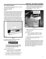
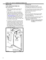
3. Locate the front set of photo eye modules. They are
mounted in the heavy-duty mounting brackets
located along the front of each side column. (The
rear set of eyes is installed inside the columns.)
(See Figure 38)
4. If either bracket appears bent or out of position,
readjust the bracket as required. (The rear set of
photo eyes is mounted directly to the side columns.
It is unlikely that these eyes will ever require aligning
unless serious damage to either side column
occurs.)
5. Observe the indicator lights to verify that both sets
of photo eyes are aligned. The green light indicates
the photo eye modules are powered up. When the
yellow light on the receiver module is also lit, the
emitter and receiver modules are properly aligned.
MOTOR BRAKE ADJUSTMENT
The disconnect must be in the OFF posi-
tion and properly locked and tagged
before performing the following proce-
dure.
1. Remove the manual brake release lever.
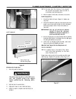
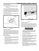
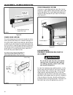
2. Loosen hex-head bolts retaining the dust cover to
the motor assembly. Remove the cover.
(See Figure 39)
Receiver
Emitter
Dust
Cover
Emitter
Dust Cover
Retaining Bolts
Receiver
A7500245
Figure 39
A8500129
Freezer Door Photo Eye Configuration
Figure 38

