15
ADJUSTMENTS
—DOOR PANEL ALIGNMENT AND ADJUSTMENT
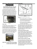
The disconnect must be in the OFF position
and properly locked and tagged before
performing the following procedure.
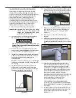
3. Unlock the door panel(s) with the Chain Release
Assembly(s).
a. On bi-parting doors, manually move the doors
so that the panels are 3 in. apart.
b. On one-way doors, manually move the door
so that it is 3 in. from the leading edge of the
bulb seal.
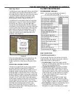
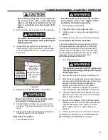
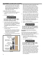
4. Check that each insulated door panel is level
along its top edge. Bi-parting door panel edges
must be at the same height across the top edge.
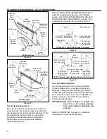
If adjustment is necessary, the sides of either
panel can be independently adjusted up or down
by loosening the lock nut, repositioning the trolley
bolt in the swivel hanger barrel, then re-
tightening the lock nut after properly adjusted.
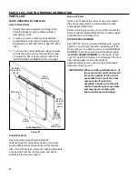
(See Figures 36 and 37)
Figure 36
Figure 37
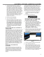
5. Once the door panel(s) are repositioned and
checked/adjusted for level and hanging straight,
check the position of the bottom edge of each
panel. The floor sweeps should just make
contact with the floor to create a seal along the
entire width of the door panel on both the front
and back sides.
6. If vertical adjustment to a panel is necessary,
adjust the panel(s) as done in the prior step.
Adjust trolley bolts equally in the same direction
so the panel remains level.
7. After each door panel is leveled by adjusting the
trolley bolts
– the lower jamb nut must be spun
up to the bottom of the trolley carriage and
torqued to 15 Ft-lbs. Failure to do this will allow
the trolley bolt to spin (loosen) which lowers the
door and eventually causes the door to drag and
excessive sweep seal wear. (See Figure 37)
8. Restore power to the door and return to service.
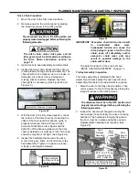
Failure to properly tighten the trolley bolt
will lead to the bolt loosening and lower the
door panel. This can cause excessive
sweep seal wear and the door panel to be
damaged and/or destroyed.
Locking the trolley bolt with the jamb nut
against the swivel hanger barrel will lead to
the door panel jumping in the trolley bolt-
carriage interface during opening and
closing cycles. This will at a minimum
cause wear to the door panel and its
components.
DOOR RETENTION/BULB SEAL ADJUSTMENT
The door seal is controlled by the door panel
alignment and contact with the bulb seal. This is
determined by the position of:
a. the door mount relative to the head assembly/
trolley track,
b. the bulb seal mounts, and
c. the door retainers/stay rollers mounted on the
floor.
This is why during installation the head assembly’s
position and alignment with the door bulb seals are
critical and how their mounting planes must be
parallel and positioned /- 0.25 inch overall.
The door seal adjustment must be done in 2
separate steps, the top header/door panel, and the
bottom door/stay rollers. (See Figure 38)
¾-10NC
trolley bolt
¾-10NC
lock nut
¾-10NC drilled
& tapped rod-
swivel hanger
barrel
Panel(s) Must Be Level
Across Top Edge and
Hang Straight
With Panel(s) 3 in.
Apart/Open, Floor
Sweep(s) Should Just
Cover/Touch Floor
Bi-Parting Door Shown/One-
Way Door Is the Same


