20
ADJUSTMENTS
—CHAIN RELEASE ASSEMBLY ADJUSTMENT
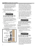
Figure 45
5. Loosen the fasteners securing the Chain
Release Assembly to the door panel. Align the
release assembly bracket chain glide with the
drive chain so the chain runs in a straight line
between the drive and idler gear sprockets.
Tighten the screws to 15 ft-lbs locking the Chain
Release Assembly in place. (See Figure 45 and
46)
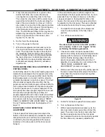
Figure 46
6. Re-check the height of the chain glide relative to
the chain and adjust if necessary. Tighten the
chain glide bracket fasteners to 15 ft-lbs. (See
Figure 46)
7. Reattach the Manual Chain Release Cable
around the 2 bolts on the Chain Release
Assembly Bracket pivot arm as shown so it is
taught. Torque the bolts to approximately 4 ft-lbs.
Test the Manual Chain Release Handle to
confirm it is working properly. (See Figure 46)
8. Restore power to the door and return to service.
9. With the assembly aligned, adjusted, and
secured, cycle the door open and closed several
times to test to verify the assembly works
properly. Then fully close the door. Make any
adjustments as necessary.
Manual Chain
Release Cable
Upper Bracket
w/ Chain Glide
Chain Glide
Chain Glide
Bracket Fasteners
Chain Release Assembly
Chain Release Assembly
Wrap Chain
Release Cable
Chain Release
Assembly Bracket
Chain Release
Assembly Door
Panel Fasteners

