background image


14 

COUPLING ATTACHMENTS TO  
THE PTO 

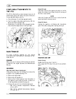
The PTO is fitted with an instant adaptor device to fit 
attachments quickly and easily. Proceed as follows to 
fit your attachments (see fig. 15): 

a.  Check that lever (1) is in disengaged position. 
b.  Push the shaft of the attachment into the PTO (2). 

Make sure that it engages fully. 

c.  Rotate lever (1) clockwise to the engaged position. 

Check that the attachment is correctly locked. 


MAINTENANCE 

To ensure continuing reliability, use only original 
spare parts when overhauling or repairing your two-
wheel tractor. 

ENGINE 

Make sure you do comply with the safety precautions 
contained in the engine Operation and Maintenance 
Manual. 

GEARBOX 

After the first 50 hours (running in) 

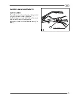
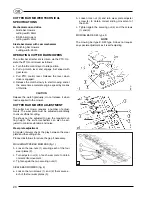
Change the oil (see fig. 16). Change the oil when the 
engine is hot to facilitate draining of oil. 

a.  Remove the right wheel. 
b.  Remove the oil dip-stick (1). 
c.  Remove the oil drain plug (3) from the bottom of 

the gearbox (right side) and let the oil drain out. 
When fully drained, reinstall the plug (3). 

d.  Fill up with new oil (1.3 l) of the following types: 

− 

SAE 90 for ambient temperatures between 
-6 and +32°C; 

− 

SAE 140 for ambient temperatures between 
+32 and +60°C. 

Every 20 hours 

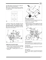
Check the oil level in the gearbox housing: to do this, 
slacken the screw (2) and check that oil is coming out 
from the screw position. 

NOTE 

Check the oil level with the motor cold and with the 
two-wheel tractor on level ground. 

Every 300 hours 

Change the gearbox oil following the instructions 
given in the above paragraph covering running in. 


POWER TAKE OFF 

Every 8 hours 

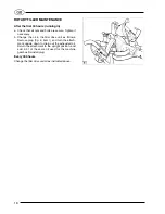
Grease the PTO (see fig. 17, item 1). 
Also grease the PTO every time you fit a new attach-
ment. 


Summary of Contents for SUPER SMART

Page 1: ...SUPER SMART SUPER SMART Diesel USE AND MAINTENANCE MANUAL GB...

Page 2: ......

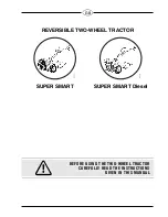
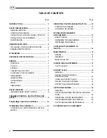
Page 3: ...GB REVERSIBLE TWO WHEEL TRACTOR SUPER SMART SUPER SMART Diesel BEFORE USING THE TWO WHEEL TRACTOR CAREFULLY READ THE INSTRUCTIONS GIVEN IN THIS MANUAL...

Page 4: ...ACTOR CONTROLS 10 OPERATING THE CONTROLS 10 CONTROLS OF FRONT MOUNTED ATTACH MENTS 11 OPERATING THE TWO WHEEL TRACTOR 12 STARTING THE ENGINE 12 STOPPING THE ENGINE 12 FITTING FRONT MOUNTED ATTACHMENTS...

Page 5: ...UDENCE Prudence is the Golden Rule to prevent accidents TRAINING The two wheel tractor must only be used by respon sible people trained in the use of the machine and duly authorized to use it MACHINE...

Page 6: ...tly lubricated avoid working for long periods on slopes steeper than 20 Do not operate the two wheel tractor if hoods or other safety devices are missing or defective Keep your hands and feet clear of...

Page 7: ...r two wheel tractor some distance away from where the spillage occurred before starting it Replace the exhaust pipe if it becomes worn or damaged EC MARKING The two wheel tractor is marked EC in compl...

Page 8: ...Models to punched on the gearbox SUPER SMART SUPER SMART Diesel A211408 A212096 Progressiv unit number starting from Progressiv unit number starting from AC00001 With SICKLE BAR MOWER cm 96 With ROTAR...

Page 9: ...e attachments and does not require the use of bolts nuts or spanner HANDLEBARS Adjustable in height and width Rotate handlebars through 180 when front mounted attachments are used WHEELS TYRES Pneumat...

Page 10: ...oon as the handlebars are released see fig 4 item 2 REVERSE SPEED SAFETY DEVICE The two wheel tractor is provided with an operator adjusted safety device see fig 3 item 1 that pre vents concurrent use...

Page 11: ...find below the adhesive transfer printing shown on the machine For accident prevention purposes they must always be clearly readable Should they be damaged it is compulsory to replace them by request...

Page 12: ...own engine running Lever 2 released engine stopped Throttle control lever See figure 5 Lever 3 in up position engine at idle Lever 3 in down position max engine rpm Gear lever two wheel tractor config...

Page 13: ...l WARNING A safety device prevents you from using the rotary til ler attachment in reverse gear Do not use the two wheel tractor if this safety device is not correctly in stalled Handlebar vertical lo...

Page 14: ...ith a cold engine is shown on the appropriate plate When starting with a hot engine the starter lever must be kept in in gear position d Press down the engine stop lever fig 10 item 1 e Pull clutch le...

Page 15: ...operate the machine in the changed direction of motion Proceed as follows a Remove the pin see fig 13 item 1 locking the gear control rod 2 b Remove the pin 3 locking the power take off rod 4 c Squee...

Page 16: ...il see fig 16 Change the oil when the engine is hot to facilitate draining of oil a Remove the right wheel b Remove the oil dip stick 1 c Remove the oil drain plug 3 from the bottom of the gearbox rig...

Page 17: ...lutch lever must have a free play of about 5 to 6 mm before the clutch starts to disengage Insufficient play can cause clutch slip while excess play can lead to failure to disengage fully Adjust play...

Page 18: ...l bath Max rotation speed 300 rpm Working width 40 to 50 cm adjustable Weight 20 700 kg WARNING The rotary tiller is provided with a safety device fitted to the attachment flange fig 1 item 2 which pr...

Page 19: ...uit new tilling width To do this remove the screws fig 4 item 1 and install the two side extensions 2 b Adjust width of matching piece 3 by use of screws 4 Tilling depth adjustment To vary tilling dep...

Page 20: ...hange the oil in the tiller drive unit as follows Remove plug fig 6 item 1 and turn the attach ment upside down to drain out the exhausted oil Return the attachment to the upright position and add 0 3...

Page 21: ...opes operate only under safe and stable conditions Do not work uphill or downhill move across the slope instead Take spe cial care when turning Do not operate on slopes over 30 NOISE In order to reduc...

Page 22: ...of adjust ments The wear plate must be adjusted periodically to ensure efficient cutting The shoes can be adjusted to give the required cut ting height The knife mechanism can also be ad justed to mi...

Page 23: ...r 3 and push rod is as required a Tighten bolts 1 again Cam mechanism movement The coupling between roller and knife mechanism does not have adjustment in case of excessive free play the wear parts mu...

Page 24: ......

Page 25: ......

Page 26: ......

Page 27: ...NA S p A TWO WHEEL TRACTOR S E P SUPER SMART BH10X00000 A211408 A212096 AC00001 42018 SAN MARTINO IN RIO RE ITALY with rotary tiller and or sickle bar mower ECC 89 392 Directives Brand Type from machi...

Page 28: ...218258 M3 VALPADANA S p A Societ unipersonale appartenente al Gruppo Industriale Argo S p A 42018 S MARTINO IN RIO RE ITALY Via Don Pasquino Borghi 6 TEL 0522 73 17 11 FAX 0522 73 17 31 E MAIL infose...

Reviews: