17
each tilling element, and by removing or adding one
tiller rotor at the end of the two tillers.
Refer to fig. 2 to determine the tiller rotor configura-
tion required to obtain the desired tilling width, then
proceed as follows.
To reverse the position of the outside tiller rotor pairs
(fig. 3, item 1), remove the four attachment nuts (2)
and invert the position of the outside pair of tiller ro-
tors, fitting the left rotor to the right and vice-versa.
Make sure you keep the cutting edge of the rotors
facing the front of the machine.
Adjustment of protection guards
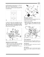
a. Adjust width of protection guards to suit new tilling
width. To do this, remove the screws (fig. 4, item
1), and install the two side extensions (2).
b. Adjust width of matching piece (3) by use of
screws (4).
Tilling depth adjustment
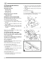
To vary tilling depth you must adjust the height of rear
tine (fig. 5, part. 1). Proceed as follows:
a. Remove nut and bolt (2).
b. Move the tine up or down until the slot on the
bracket corresponds to the desired hole on the
tine shank. Replace nut and bolt (2) and fully
tighten.
Ground adjustment
Adjust the position of the rotary tiller as follows to en-
sure correct movement over different types of ground:
HARD GROUND
If the tiller tends to jump on hard ground, lower the
tine to lift the rotary tiller.
SOFT GROUND
If the tiller tends to sink in on soft ground, lower the
tine to move the centre of gravity over the machine
wheels.
Summary of Contents for SUPER SMART
Page 1: ...SUPER SMART SUPER SMART Diesel USE AND MAINTENANCE MANUAL GB...
Page 2: ......
Page 24: ......
Page 25: ......
Page 26: ......

