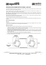

3. Allow smoke from a cotton wick or a punk to enter the
detector’s sensing chamber for at least 10 seconds.
When sufficient smoke has entered the chamber, an
alarm signal
would be triggered by illuminating t
he
LED. After
the
alarm
is triggered
,
r
eset each
detector and/or control unit before
attempting to
test the additional detectors in the same
zone. If the
alarm fails in this step, it indicates a
defective unit,
which
would
require service.
HEAT SENSOR TESTING
T
o test the detector, it
should be subject to a flow of
warm air at a temperature between
284F and 356F
(
140
C
and 180.
C).
Some domestic hair dryers can meet
this
requirement. Proceed as follows:
1. Switch on the warm airflow and check that
the
temperature
is correct and stable.
2.
3.
D
irect the airflow at the
guard protecting the
thermistor. The detector shoul
d be triggered
within 30
seconds.
When
the
alarm is on, immediately remove the
heat
source and check that the detector’s red LED
is
on
.
Reset the detector from the control panel.
4.
If the detector fails
to trigger the
alarm within 30
seconds
,
it
would mean that it should be returned to the
distributor for servicing to adjust its sensitivity.
5.
After testing
,
check that the system is set for
normal
operation and notify the appropriate authorities
that the
testing operation is complete and the system
is active
again.
NOTES FOR USING DETECTOR
The National Fire Protection Association (NFPA)
states that duct smoke detector must not used as a
substitute for open area smoke detector
s
. Duct
smoke detector
s are
solely intended to use in the
air handing equipments for such purposes like
dampers or shutting down the air handing units.
NOT SUITABLE FOR INSTALLATION IN
AREAS WHERE AIR VELOCITIES EXCEED
300 ft/min.
MAINTENANCE
The recommended minimum requirement for detector
maintenance consists of an annual cleaning of
the
dust
from the detector head by using a vacuum
ing routine
compliant with the
NFPA-72A standard.
CAUTION: DO NOT ATTEMPT TO REMOVE
THE SCREWS WHICH HOLD THE ASSEMBLY
OF
THE
SMOKE-SENSING CHAMBER AND PRINTED
CIRCUIT BOARD (PCB). THIS ASSEMBLY IS
SEALED FOR YOUR PROTECTION AND IS NOT
INTENDED TO BE SEPARATED FOR SERVICING BY
USERS. OPENING SUCH ASSEMBLY WILL VOID
THE WARRANTY.
REFER TO THE TECHNICAL BUL
E
TIN ISSUE
NO. STSD20080702S01, REV.D, July 02, 2008
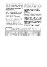
SPECIFICATION
Model
2/4
wire
Heat
Sensor
Setting
Voltage
DC
(Min./Max.)
Standby
Current
(Max.)
Alarm
Current
(12/24V)
Surge
Current
(Max.)
Start-Up
Time
(Max.)
Permissible
Current
(Max.)
Cycle
Time
Alarm
contact
Base
Model No.
SF119-4H(12V)
4
135
±
5
12V
80
μ
A
30mA
-
30 Sec.
-
1-3 Sec.
Form A
P/N854001
SF119-4H(24V)
4
135
±
5
24V
80
μ
A
45mA
-
30 Sec.
-
1-3 Sec.
Form A
P/N854001
SF119-4 (12V)
4
-
12V
80
μ
A
30mA
-
30 Sec.
-
1-3 Sec.
Form A
P/N854001
SF119-4 (24V)
4
-
24V
80
μ
A
45mA
-
30 Sec.
-
1-3 Sec.
Form A
P/N854001
SF119-2HL
2
135
±
5
10.8~33V 80
μ
A
22/55mA
160
μ
A
30 Sec.
80mA
1-3 Sec.
—
P/N854001
SF119-2L
2
-
10.8~33V 80
μ
A
22/55mA
160
μ
A
30 Sec.
80mA
1-3 Sec.
—
P/N854001
SF119-2H
2
135
±
5
10.8~33V 80
μ
A
22/55mA
160
μ
A
30 Sec.
80mA
1-3 Sec.
—
P/N852001
SF119-2
2
-
10.8~33V 80
μ
A
22/55mA
160
μ
A
30 Sec.
80mA
1-3 Sec.
—
P/N852001
Remark: L-
remote indicator output;
H-
Heat sensor;
AR-
Auto-reset;
B-
Sound
2-wire devices are UL Recognized, the 4-wire devices are UL Listed