11
12VAC
13VAC
POWER INPUT
NEUTRAL
POWER INPUT
POWER INPUT
GROUN
D
COM
GROUN
D
GND
GND
12V
N
L/V
H
13V
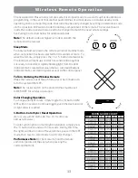
Output Wiring Locations
3. Using a hole saw, open the knockout for the size of the conduit (¾" or 1") being installed.
4. Bring output conduits to the open conduit locations. Any conduit used as output wiring runs
between the lights and pLX-Plus unit (p/n pLX-PL60/PL100) and any external controller
shall be Non-Metallic (Polymeric).
ATTENTION: LES CONDUITS DOIVENT ÊTRE RELIÉS PAR LA MASSE
5. Attach an approved ‘rain-tight’ or ‘wet location’ hub to the conduit first, and then attach hub
to the enclosure.
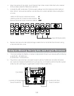
6. The poolLUX Power has has two low voltage electrical output terminals (Taps) or
connection points that allow for 12VAC or 13VAC operation. Securely connect the lights’
two conductors to the electrical (taps) output terminals. Most installations will utilize the
terminal configuration of 12VAC terminal and low voltage common terminal. In some
cases additional voltage may be required to operate the lights requiring use of the 13VAC
terminal and the low voltage common terminal.
*Note:
DO NOT use or bridge both the 12VAC and
13VAC terminal positions at the same time.
7. Do a final inspection to verify all wiring connections
are correct.
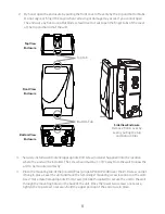
8. Once inspected, align the panel bayonet guides to the
snap-in receivers along the centerline of the enclosure.
Evenly and gently, push the cover in place ensuring
that both the top and bottom latches ‘snap’ in place.
9. Apply power from the input supply voltage to the
unit and function test the unit via the two-way rocker
switch on the upper, right side of the unit.
CAUTION – IF USING FEEDER OR SUPPLY LINES TO A JUNCTION BOX, BE SURE TO USE THE
APPROPRIATE WIRE GAUGE FOR THE LOAD AND DISTANCES INVOLVED.
or
Summary of Contents for pLX-PL60
Page 2: ...2 ...


