7
Connect 120VAC power INPUT wiring to the unit’s 3-wire cage clamp.
1. Place the unit on the opti onal PT-BASE or the existi ng base from the previous illuminator. Pull the supply
cable unti l it extends beyond the end of the conduit in the base from 6 to 8ʺ. Att ach the PT-6002 to the
base with 2 of the supplied screws.
2. Strip the jacket back 4ʺ back from the end of the internal wires.
3. Strip the insulati on on each wire (black, white, and green) to 3/8ʺ +/- 1/16ʺ.
4. Feed the cable and stripped wires through the white nylon fi nger grommet and dress it approximately as
shown.
5. Connecti ons (GFCI protected power must be provided to the unit):
a. The black (hot) wire connects to the terminal block orange segment,
b. the white wire (common) to the grey segment, and
c. the green wire (ground) to the yellow-green segment.
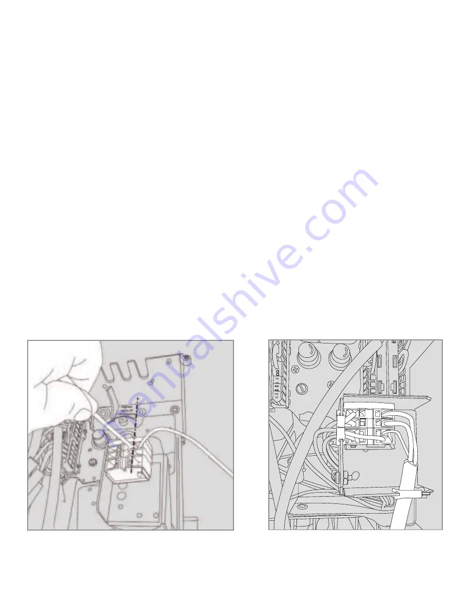
6. Connect each wire to its correct segment (
Figure B
):
a. Fully insert the wire installati on tool (supplied) into the segment’s smaller square hole.
b. Firmly lever the tool to the left to open the wire entry and hold it in place.
c. Fully insert the correct (matching) wire into the segment’s larger square hole.
d. Release the installati on tool and remove it.
e. Pull the inserted wire fi rmly to confi rm that it is ti ghtly gripped.
7. Aft er all three wires are inserted, dress them so they do not interfere with each other, as shown in
Figure C.
8. Dress the cable to remove any excessive loops and/or kinks.
Att enti on – Do Not Lose the provided Installati on Tool, it is required for removal of the input wires should
service or replacement be required.
FIGURE B (Steps 6a-6e): Installati on tool use – Insert fully, lever towards
the left , insert wire, release tension by moving tool to the right, remove
tool, & pull test wire
FIGURE C (Steps 7 & 8): Cage clamp shown with 120VAC
input wires in place (connected and dressed, right side)
Summary of Contents for Power Tower PT-6002
Page 2: ...2...


