Measuring principle of HVAC temperature sensors in general:
The measuring principle of temperature sensors is based on an internal sensor that outputs a temperature-dependent resistance signal.
The type of the internal sensor determines the output signal. The following active ⁄ passive temperature sensors are distinguished:
a) Pt 100 measuring resistor (according to DIN EN 60 751)
b) Pt 1000 measuring resistor (according to DIN EN 60751)
c) Ni 1000 measuring resistor (according to DIN EN 43 760, TCR = 6180 ppm ⁄ K)
d) Ni 1000_TK 5000 measuring resistor (TCR = 5000 ppm ⁄ K)
e) LM235Z, semiconductor IC (10 mV ⁄ K, 2.73 V ⁄ °C). Ensure correct po ⁄– when connecting!
f) NTC (according to DIN 44070)
g) PTC
h) KTY silicon temperature sensors
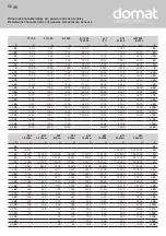
The most important resistance characteristics are shown on the last page of these operating instructions. According to their characteristics, individual
temperature sensors exhibit different slopes in the range between 0 °C and +100 °C (TK value). Maximum-possible measuring ranges also vary from
sensor to sensor (for some examples to this see under technical data).
Design of HVAC temperature sensors in general:
Sensors are distinguished by shape type as follows: surface-contacting sensors, cable temperature sensors, and housing-type and built-in temperature
sensors.
– On surface-contacting sensors, the temperature sensor has at least one contact area that must be brought in contact, e.g. with the surface of radia-
tors or pipes. If the contact area is not positioned correctly relative to the surface to be measured, significant temperature measurement errors may
occur. Good contact area and temperature conduction must be ensured, dirt and unevenness must be avoided, and heat-conductive paste is to be
used where necessary.
– On cable temperature sensors, the temperature sensor is installed inside a sensor sleeve, from which a connecting cable is leading out. In addition
to the standard insulating materials PVC, silicone, and fibreglass with stainless steel texture, other versions are also available that may allow a wider
range of application.
– On housing-type sensors, the temperature sensor is embedded in a respective housing. Different designs of enclosures are available, e.g. with an
external sensor sleeve (see outside temperature sensor ATF2). Housing-type sensors are normally distinguished into in-wall (FSTF) and on-wall (RTF,
ATF) types and indoor and wet room versions. Connection terminals are placed on a plate inside the connecting housing.
– Duct and built-in temperature sensors are distinguished into temperature sensors with interchangeable measuring insert and without interchangeable
measuring insert. Connection parts are placed inside a connecting head. Standard process connection for immersion sensors is a pipe thread (sizes in
inches) and a mounting flange for duct sensors. However, it may be designed differently. When a built-in sensor has a neck tube, the application range
is usually somewhat wider since ascending heat cannot flow directly and immediately into the connecting head. This is to be noted especially when
transmitters are installed. The temperature sensor in built-in sensors is always placed inside the front part of the protective tube. On temperature
sensors with short reaction times, protective tubes are stepped.
Note!
Select immersion depth for built-in sensors so that the error caused by heat dissipation stays within the admissible error margins. A standard value is: 10
x diameter of protection tube + sensor length. In connection with housing-type sensors, particularly with outdoor sensors, please consider the influence
of thermal radiation. For that purpose, a sunshade and radiation protector SS-02 can be attached.
G
General notes
Component ......................................................................... max. thermal load
Connecting cable
PVC, normal ..............................................................................................+70 °C
PVC, heat-stabilized ............................................................................. +105 °C
Silicone ................................................................................................... +180 °C
PTFE ....................................................................................................... +200 °C
Fibreglass insulation with stainless steel texture ........................ +400 °C
Housing ⁄ Sensor
see table "Technical Data"
Maximum thermal load on components:
On principle, all temperature sensors shall be protected
against unacceptable overheating!
Standard values for individual components and materials
selected are shown for operation under
neutral atmos phere and otherwise normal conditions
(see table to the right).
For combinations of different insulating materials,
the lowest temperature limit shall always apply.
G
Resistance characteristics of passive temperature sensors (see last page)
In order to avoid damages ⁄ errors, preferably shielded cables are to be used.
Laying measuring cables parallel with current-carrying cables must in any case be avoided. EMC directives shall be observed!
These instruments must be installed by authorised specialists only!
ATTENTION, NOTE ! Testing current influences the thermometer‘s
measuring accuracy due to intrinsic heating and therefore, should
never be greater than as specified below:
Sensor current, maximum
I
max
Pt1000 (thin-layer) ............................................................................ < 0.6 mA
Pt100 (thin-layer) ........................................................................... < 1.0 mA
Ni1000 (DIN), Ni1000 TK5000 ....................................................... < 0.3 mA
NTC xx ...................................................................................................... < 2 mW
LM235Z ....................................................................................... 400 µ A … 5 mA
KTY 81 - 210 .............................................................................................. < 2 mA
Limiting deviation according to classes:
Tolerances at 0 °C:
Platinum sensors (Pt100, Pt1000):
DIN EN 60751, class B ........................................................................ ± 0.3 K
1 ⁄ 3 DIN EN 60751, class B .................................................................± 0.1 K
Nickel sensors:
NI1000 DIN EN 43760, class B .............................................................. ± 0.4 K
NI1000 1 ⁄ 2 DIN EN 43760, class B ..................................................... ± 0.2 K
NI1000 TK5000 ................................................................................... ± 0.4 K
Summary of Contents for 1101-40A0-1003-000
Page 7: ......


