14
G
Installation and Commissioning
Putting in operation
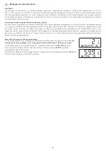
After switching on the device, a self-test and tempering period follows.
This procedure takes 30 - 50 minutes,depending on the ambient conditions.
During this time the output analogue voltage differs from the actual measured value.
Manual calibration can then be performed as an option.
Make sure that no harmful substances influence the calibration process and that the sensor is operated in fresh air.
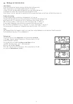
Switching point setting
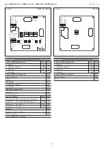
A potential-free changeover contact is available as a switch output.
A switching point between 10 % and 95 % of the measuring range can be selected using
the SET potentiometer. The 10 % value is added to the fresh air limit of 400 ppm for CO2.
(600...1900 ppm with MR = 0...2000 ppm or 900...4700 ppm with MR = 0...5000 ppm).
With other measurands, the corresponding lower limit is used directly as a basis.
(PM: 10 %...95 % of measuring range µg / m³, Temperature: +5...+48 °C, Humidity: 10...95 % r.H.)
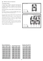
The assignment of the switch output to measurand is done via DIP switch (DIP 7 and DIP 8).
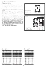
Offset
Each measuring channel (except for particulate sensor) has a separate offset potentiometer for subsequent adjustment of the measurement.
The adjusting range is ± 10 % of the measuring range.
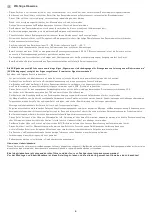
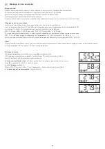
Display
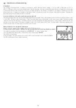
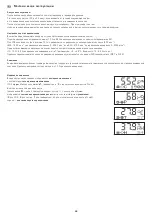
In the first line, the
measurements
with the corresponding
units
( CO2 in
ppm
, fine dust in
µg ⁄ m³,
temperature in
°C
, relative humidity in
% r.H.
)
are displayed in a cyclical series.
In the second line, the
switching status of the relay
is shown on the left as a circuit
(full
●
= relay energised; empty
○
= relay de-energised)
followed by the corresponding
indicator
(
C
for CO2;
P
for particle;
T
for temperature;
H
for relative humidity in
% r.H.
)
and the
switchpoint value
is shown on the right.

