background image

15

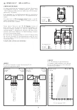
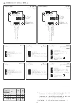
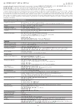
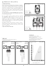
 Load resistance diagram 

AFF - xx  ⁄  AFTF - xx 

4...  20 mA

800

700

600

500

400

300
250

50

200

10

15

20

25

30 35 36 40

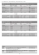
Load resistance diagram

W

orking r

esis

tanc

e  (Ohm)

Operating voltage  (V DC)

Admissible

  range

800

700

600

500

400

300
250

50

200

10

15

20

25

30 35 36 40

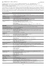
Load resistance diagram

W

orking r

esis

tanc

e  (Ohm)

Operating voltage  (V DC)

Admissible

  range

NOTE

For 4...20 mA devices, DC voltage must be used  
(without residual  ripple, see permissible range of load 
resistance diagram). Do not use pulsating DC voltage.

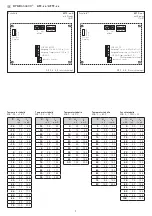
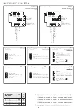
Connecting diagram 

AFTF - xx - U 

Output: 


with  ⁄ without


0 -10 V


Display

Connecting diagram 

AFTF - xx - I  

Output: 


with  ⁄ without


4...20  mA 

Display

NOTE

At transmitters with current output the humidity output (Pin 2)  
must categorically be connected !

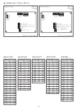
1 2 3 4

230V AC

24V AC/DC

PLC

PC

+U

24

AC

/D

C

O

ut

pu

t h

um

id

ity 

in 

r.H

. 0

-1

0V

O

ut

pu

t t

em

pe

ra

tu

re 

in 

°C 

0-

10

V

–UB

-GN

D

1 2 3 4

230V AC

24V DC

+U

24

D

C

O

ut

pu

t h

um

id

ity 

in 

r.H

. 4

...

20m

A

O

utp

ut

 tem

per

at

ur

in

 °

C

 4

...

20m

A

PLC

Working

resistance

–UB  GND  (optional f

or

LCD back

gr

ound lightling)

Connecting scheme 

Parallel operation

Connecting scheme 

Individual operation

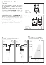
SUPPLY VOLTAGE:

For operating voltage reverse polarity protection, a one-way rectifier or 
reverse polarity protection diode is integrated in this device variant. 


This internal one-way rectifier also allows operating 0 - 10 V devices on AC 
supply voltage.

The output signal is to be tapped by a measuring instrument. Output volt-
age is measured against zero potential (O V) of the input voltage!

When this device is operated on 

DC supply voltage

, the operating voltage 

input UB+ is to be used for 15...36 V DC supply and UB – or GND for ground 
wire!

When several devices are supplied by one 24 V

 AC voltage supply

, it is to 

be ensured that all ”positive“ operating voltage input terminals (+) of the 
field devices are connected with each other and all ”negative“ operating 
voltage input terminals (–) (= reference  potential) are connected together 
(in-phase connection of field devices). All outputs of field devices must be 
referenced to the same potential!

In case of reversed polarity at one field device, a supply voltage short- 
circuit would be caused by that device. The consequential short-circuit 
current flowing through this field device may cause damage to it.

Therefore, pay attention to correct wiring!

Circuitry

Circuitry

0...10V

0V/GND

0...10V

0V/GND

Power supply

AC 24V~ 

0V

DC 15-36V =  GND

Circuitry

0...10V

0V/GND

V

Power supply

AC 24V~ 

0V

DC 15-36V =  GND

HYGRASGARD

®

    AFF - xx  ⁄  AFTF - xx
Summary of Contents for HYGRASGARD AFF Series

Page 1: ...assivem Ausgang G Operating Instructions Mounting Installation On wall humidity and temperature sensors 1 8 2 0 calibratable with multi range switching and active passive output F Notice d instruction...

Page 2: ...TF 2 0 AFF 20 AFTF 20 1 8 Tyr2 35 50 126 90 112 20 4 M16x1 5 16 137 35 112 20 4 M16x1 5 16 211 SF K Kunststoff Sinterfilter Standard Plastic sinter filter standard Filtre fritt en mati re synth tique...

Page 3: ...0 95 r H ohne Betauung zul ssige Luftfeuchte 95 r H nicht kondensierende Luft Abweichung Feuchte AFF AFTF AFF SD AFTF SD typisch 2 0 20 80 r H bei 25 C sonst 3 0 AFF 20 AFTF 20 AFF 25 AFTF 25 typisch...

Page 4: ...0 r H 4x wie oben 0 10 V 0 10 V Pt1000 1201 7111 2005 000 AFTF U NI1000 0 100 r H 4x wie oben 0 10 V 0 10 V Ni1000 1201 7111 2009 000 AFTF U NITK 0 100 r H 4x wie oben 0 10 V 0 10 V Ni1000TK5000 1201...

Page 5: ...1 0400 101 AFTF 25 xx aktiv AFTF 25 I T YR 2 0 100 r H 35 75 C 35 35 C 0 50 C 0 80 C 4 20 mA 4 20 mA 1201 7132 1000 101 AFTF 25 I T YR 2 DISPLAY 0 100 r H 4x wie oben 4 20 mA 4 20 mA 1201 7132 1400 10...

Page 6: ...passives Element UB GND Ausgang Temperatur 0 10V in C Ausgang Feuchte 0 10V in r H UB 24V AC DC z B Pt1000 Ni1000 LMZ235Z 1 2 3 4 5 6 passives Element UB GND optional f r Hintergrundbeleuchtung Ausgan...

Page 7: ...9 45 7 3 15 6 50 7 7 16 4 55 8 2 17 1 60 8 6 17 8 65 9 1 18 5 70 9 5 19 2 75 10 0 20 0 Temperaturtabelle MB 35 35 C C UA in V IA in mA 35 0 0 4 0 30 0 7 5 1 25 1 4 6 3 20 2 1 7 4 15 2 9 8 6 10 3 6 9...

Page 8: ...r tevariante eine Einweggleichrichtung bzw Verpolungschutzdiode integriert Diese interne Einweggleichrichtung erlaubt auch den Betrieb mit AC Versorgungs spannung bei 0 10 V Ger ten Das Ausgangssignal...

Page 9: ...Dieses Ger t ist nur f r den angegebenen Verwendungszweck zu nutzen dabei sind die entsprechenden Sicherheitsvorschriften des VDE der L nder ihrer berwachungsorgane des T V und der rtlichen EVU zu bea...

Page 10: ...n Permissible air humidity 95 r H non precipitating air Deviation humidity AFF AFTF AFF SD AFTF SD typically 2 0 20 80 r H at 25 C otherwise 3 0 AFF 20 AFTF 20 AFF 25 AFTF 25 typically 1 8 10 90 r H a...

Page 11: ...AY 0 100 r H 4 20 mA 1201 7112 0400 000 AFF U T YR 2 0 100 r H 0 10 V 1201 7111 0000 000 AFF U T YR 2 DISPLAY 0 100 r H 0 10 V 1201 7111 0400 000 AFTF xx active AFTF I T YR 2 0 100 r H 35 75 C 35 35 C...

Page 12: ...0 100 r H 0 10 V 1201 7131 0400 101 AFTF 25 xx active AFTF 25 I T YR 2 0 100 r H 35 75 C 35 35 C 0 50 C 0 80 C 4 20 mA 4 20 mA 1201 7132 1000 101 AFTF 25 I T YR 2 DISPLAY 0 100 r H 4x as above 4 20 mA...

Page 13: ...n r H 0 10V UB 24V AC DC 1 2 3 4 5 6 Passive element UB GND Output temperature in C 0 10V Output humidity in r H 0 10V UB 24V AC DC e g Pt1000 Ni1000 LMZ235Z 1 2 3 4 5 6 Passive element UB GND optiona...

Page 14: ...7 3 15 6 50 7 7 16 4 55 8 2 17 1 60 8 6 17 8 65 9 1 18 5 70 9 5 19 2 75 10 0 20 0 Temperature table MR 35 35 C C UA in V IA in mA 35 0 0 4 0 30 0 7 5 1 25 1 4 6 3 20 2 1 7 4 15 2 9 8 6 10 3 6 9 7 5 4...

Page 15: ...reverse polarity protection a one way rectifier or reverse polarity protection diode is integrated in this device variant This internal one way rectifier also allows operating 0 10 V devices on AC su...

Page 16: ...ed and EMC directives are to be observed This device shall only be used for its intended purpose Respective safety regulations issued by the VDE the states their control authorities the T V and the lo...

Page 17: ...t 0 100 h r sortie correspond 0 10 V ou 4 20 mA Plage de service humidit 0 95 h r sans condensation Humidit d air admissible 95 h r sans condensation de l air Incertitude de mesure AFF AFTF AFF SD AFT...

Page 18: ...t 0 10 V 0 10 V Pt1000 1201 7111 2005 000 AFTF U NI1000 0 100 h r 4x comme plus haut 0 10 V 0 10 V Ni1000 1201 7111 2009 000 AFTF U NITK 0 100 h r 4x comme plus haut 0 10 V 0 10 V Ni1000TK5000 1201 71...

Page 19: ...00 201 AFTF 20 xx actif AFTF 20 I T YR 2 0 100 h r 35 75 C 35 35 C 0 50 C 0 80 C 4 20 mA 4 20 mA 1201 7112 1000 201 AFTF 20 I T YR 2 DISPLAY 0 100 h r 4x comme plus haut 4 20 mA 4 20 mA 1201 7112 1400...

Page 20: ...umidity in r H 0 10V UB 24V AC DC e g Pt1000 Ni1000 LMZ235Z 1 2 3 4 5 6 Passive element UB GND optional for backlighting Output temperature in C 4 20mA Output humidity in r H 4 20mA UB 24V DC e g Pt10...

Page 21: ...7 3 15 6 50 7 7 16 4 55 8 2 17 1 60 8 6 17 8 65 9 1 18 5 70 9 5 19 2 75 10 0 20 0 Tableau de temp rature plage de mesure 35 35 C C UA en V IA en mA 35 0 0 4 0 30 0 7 5 1 25 1 4 6 3 20 2 1 7 4 15 2 9...

Page 22: ...sion de polarit c d elle comprend un redressement demi onde diode de re dressement Gr ce cette diode de redressement int gr e les appareils 0 10 V peuvent galement tre aliment s en courant alternatif...

Page 23: ...ll le avec des c bles de puissance les directives CEM sont respecter Cet appareil ne doit tre utilis que pour l usage qui est indiqu en respectant les r gles de s curit correspondantes de la VDE des L...

Page 24: ...20 I 35 35 C 35 75 C 0 50 C 0 80 C 0 10 B 4 20 AFF AFTF AFF 20 AFTF 20 AFF 25 AFTF 25 35 85 C 30 80 C AFF SD AFTF SD 35 85 C 30 70 C AFF AFTF 0 4 K 25 C AFF 20 AFTF 20 AFF 25 AFTF 25 0 2 K 25 C AFF SD...

Page 25: ...0 10 0 10 Pt1000 1201 7111 2005 000 AFTF U NI1000 0 100 4 0 10 0 10 Ni1000 1201 7111 2009 000 AFTF U NITK 0 100 4 0 10 0 10 Ni1000TK5000 1201 7111 2010 000 AFTF U LM235Z 0 100 4 0 10 0 10 LM235Z 10 K...

Page 26: ...8 Premium WG02 AFF 20 xx AFF 20 I T YR 2 0 100 4 20 A 1201 7112 0000 201 AFF 20 I T YR 2 DISPLAY 0 100 4 20 A 1201 7112 0400 201 AFF 20 U T YR 2 0 100 0 10 1201 7111 0000 201 AFF 20 U T YR 2 DISPLAY 0...

Page 27: ...Ni1000 LMZ235Z 1 2 3 4 UB GND Output temperature in C 0 10V Output humidity in r H 0 10V UB 24V AC DC 1 2 3 4 Output temperature in C 4 20mA Output humidity in r H 4 20mA UB 24V DC UB GND optional for...

Page 28: ...3 5 35 6 4 14 2 40 6 8 14 9 45 7 3 15 6 50 7 7 16 4 55 8 2 17 1 60 8 6 17 8 65 9 1 18 5 70 9 5 19 2 75 10 0 20 0 35 35 C C UA B IA A 35 0 0 4 0 30 0 7 5 1 25 1 4 6 3 20 2 1 7 4 15 2 9 8 6 10 3 6 9 7 5...

Page 29: ...e 4 20 AFTF xx U 0 10 AFTF xx I 4 20 A 2 1 2 3 4 230V AC 24VAC DC PLC PC UB 24V AC DC Output humidity in r H 0 10V Output temperature in C 0 10V UB GND 1 2 3 4 230V AC 24V DC UB 24V DC Output humidity...

Page 30: ...30 r 0 100 0 10 4 20 10 0 99 9 0 10 24 ZVEI VDE EMV...

Page 31: ...bserved We warrant the faultless quality of our products as stated in our General Terms and Conditions Sous r serve d erreurs et de modifications techniques Toutes les informations correspondent l tat...

Page 32: ...Plastic sinter filter standard Filtre fritt en mati re synth tique standard 43 3 14 8 14 8 107 72 M16x1 5 35 35 55 16 37 8 M16x1 5 39 49 4 3 64 64 43 3 14 8 14 8 107 72 M16x1 5 35 35 55 16 37 8 M16x1...

Reviews: