background image

27

HYGRASGARD

®

  RFTF - Modbus

 |  Configuration


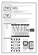
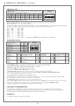
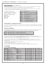
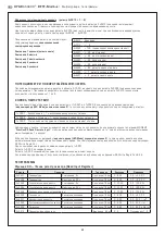
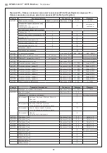
ADRESSE DU BUS

Adresse du bus 


(code binaire, valance réglable de 1 à 247)

MODBUS

Interrupteur DIP [A]

DIP 1 

DIP 2

DIP 3 

DIP 4 

DIP 5 

DIP 6 

DIP 7

DIP 8 

1 2 3 4 5 6 7 8

ON

DIP A

128

64

32

16

8

4

2

1

O N

O N

OFF

OFF

OFF

OFF

OFF

O N

suit l'adresse Modbus  128 + 64 + 1 = 193

L'adresse de l'appareil

 dans une plage de 

1 à 247

 (format binaire) est réglée via l'interrupteur DIP [A].  

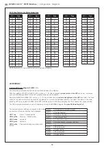
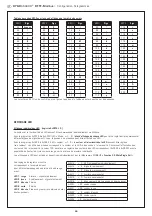
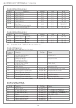
Position interrupteur 1 à 8 – voir tableau au verso !
L'adresse 0 est réservée pour des messages de broadcast, les adresses dépassant 247 ne doivent pas être occupées et sont 

ignorées par l'appareil. Les interrupteurs DIP sont codés en binaire avec les valences suivantes :
DIP 1 = 

128

 ............  DIP 1 = 

ON


DIP 2 = 

64

 ............  DIP 2 = 

ON


DIP 3 =  32 ............  DIP 3 = OFF 

DIP 4 =  16 ............  DIP 4 = OFF 

DIP 5 = 

8 ............  DIP 5 = OFF  

DIP 6 = 

4 ............  DIP 6 = OFF  

DIP 7 = 

2 ............  DIP 7 = OFF 

DIP 8 = 

1

 ............  DIP 8 = 

ON


L'exemple montre 

128 + 64 + 1 = 193

 comme adresse Modbus.

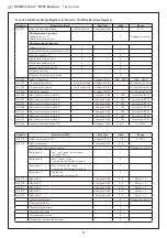
PARAMÈTRES DU BUS

Taux de transfert 

(réglable)

DIP  

DIP  

2

MODBUS

Interrupteur DIP [B]

  9600 Baud

O N

OFF

1 2 3 4 5 6

ON

DIP B

19200 Baud

O N

O N

38400 Baud

OFF

O N

réservé

OFF

OFF

Parité 

(réglable)

DIP 

3

Protection par parité 

(on / off)

DIP 

4

8N1-Modus 

(on / off)

DIP 

5

Terminaison de bus 

(on / off)

DIP 

6

EVEN   

(pair)

O N

actif   

(1 bit stop)

O N

actif

O N

actif

O N

ODD   

(impair)

OFF

inactif   

(2 bit stop)

OFF

inactif (par défaut)

OFF

inactif  

OFF

Le taux de Baud

 (vitesse de transfert) est réglé via les pos. 1 et 2 de l'interrupteur DIP [B].  

On peut régler 9600 Baud, 19200 Baud ou 38400 Baud – voir tableau !

La parité

 est réglée via la pos. 3 de l'interrupteur DIP [B].  

On peut régler 

EVEN (paire)

 ou 

ODD (impaire)

 – voir tableau !

La protection par parité

 (sécurité par parité) est activée via la pos. 4 de l'interrupteur DIP [B].  

On peut régler une correction d'erreur (sécurisation par parité) 

active (1 bit d'arrêt)

 ou 

inactive (2 bits d'arrêt)

,  

c.-à.-d. aucune sécurisation par parité – voir tableau !
Le mode 8N1 est activé via la pos. 5 de l'interrupteur DIP [B]. 

Le fonctionnement de la pos. 3 (parité) et de la pos. 4 (protection par parité) de l'interrupteur DIP [B] est ainsi désactivé. 

8N1 est réglable en mode actif ou inactif (par défaut) – voir tableau !

La terminaison du bus

 est activée par la pos. 6 de l'interrupteur DIP [B].  

On peut régler 

active

 (résistance de terminaison de bus de 120 Ohm) ou 

inactive

 (pas de terminaison de bus) – voir tableau !

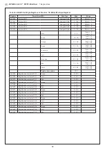
En cas de modification des paramètres du bus et de l'adresse du bus, les appareils avec 

affichage sur écran


affichent les paramètres correspondants à l'écran pour env. 30 secondes.

AFFICHAGE DE COMMUNICATION

La communication est signalée par deux voyants DEL. Les télégrammes dont la réception est bonne sont signalés  

indépendamment de l'adresse de l'appareil par l'allumage du voyant vert. Les télégrammes erronés ou les télégrammes  

d'exception Modbus déclenchés sont représentés par l'allumage du voyant rouge.

DIAGNOSTIC

La fonction de diagnostic de défauts est intégrée 

Summary of Contents for HYGRASGARD RFTF-Modbus

Page 1: ...us Anschluss G Operating Instructions Mounting Installation Roomoperating humidity and temperaturesensor 2 on wall for temperature relative absolute humidity dew point mixture ratio enthalpy calibrata...

Page 2: ...h potentiometer push buttons rotary switches and LED display avec potentiom tre poussoir commutateur rotatif et affichage LED RFTF Modbus mit Display with display avec cran c RFTF Modbus P T 5L mit Di...

Page 3: ...ienwerte erfolgt ber die Bus Schnittstelle Modbus TECHNISCHE DATEN Spannungsversorgung 24 V AC 20 und 15 36 V DC Leistungsaufnahme 1 VA 24 V DC 2 2 VA 24 V AC Sensor digitaler Feuchtesensor mit integr...

Page 4: ...H default 0 80 g kg MV 0 80 g m3 a F 0 85 kJ kg ENT 20 80 C TP 0 50 C Modbus 1201 42B6 6000 000 RFTF MODBUS LCD 0 100 r H default 0 80 g kg MV 0 80 g m3 a F 0 85 kJ kg ENT 20 80 C TP 0 50 C Modbus 12...

Page 5: ...s OFF inaktiv default OFF inaktiv OFF Die Baudrate bertragungsgeschwindigkeit wird ber Pos 1 und 2 des DIP Schalters B eingestellt Einstellbar sind 9600 Baud 19200 Baud oder 38400 Baud siehe Tabelle D...

Page 6: ...auch im Dot Matrix Bereich programmiert werden Somit k nnen auch beispielsweise Meldungen von der SPS angezeigt werden F r die individuelle Anzeige muss das Register 4x0001 physikalischer Anzeigewert...

Page 7: ...t werden Dauerlicht verschiedene Blinkarten bzw der Pr senztaster der LED zugeordnet werden ber die Register 4x0020 bis 4x0024 LED x Farbe x 1 5 kann die Farbe und Helligkeit der LED vorgegeben werden...

Page 8: ...ster freigegeben 1 Erkennung ber Flankenwechsel 1x0003 Tasterstatus aktueller Tasterzustand zum Abfragezeitpunkt Die Tasterinformationen die durch Flankenwechsel ausgel st werden sind bis zur n chsten...

Page 9: ...chen 4x0008 Dot Matrix Zeichen C Unsigned 8 Bit 0 255 ASCII Zeichen 4x0009 Dot Matrix Zeichen D Unsigned 8 Bit 0 255 ASCII Zeichen 4x0010 Dot Matrix Zeichen E Unsigned 8 Bit 0 255 ASCII Zeichen 4x0011...

Page 10: ...ll 39 Gelbgr n 40 49 dunkel 40 hell 49 Gr n 50 59 dunkel 50 hell 19 T rkis 60 69 dunkel 60 hell 69 Blau 70 79 dunkel 70 hell 79 Violett 80 89 dunkel 80 hell 89 Farbregister 100 4x0025 LED 1 Farbregist...

Page 11: ...unction Code Parameter Data Type Antwort 00 Echo der Sendedaten Loopback Echodaten 01 Neustart Modbus Reset Listen Only Mode Echo Telegramm 04 Aktivierung Listen Only Mode Keine Antwort 10 L sche Z hl...

Page 12: ...trennte Segmente aufzuteilen Die Teilnehmeradresse kann von 1 bis 247 eingestellt werden F r die Busleitung ist ein Kabel mit paarverseilter Datenleitung Spannungsversorgung und Kupferabschirmgeflecht...

Page 13: ...Originalverpackung angenommen Eine Inbetriebnahme ist zwingend durchzuf hren und darf nur von Fachpersonal vorgenommen werden Vor der Montage und Inbetriebnahme ist diese Anleitung zu lesen und die al...

Page 14: ...supply 24 V AC 20 and 15 36 V DC Power consumption 1 VA 24 V DC 2 2 VA 24 V AC Sensor Digital humidity sensor with integrated temperature sensor low hysteresis high long term stability Data points Tem...

Page 15: ...R 0 80 g m3 A H 0 85 kJ kg ENT 20 80 C DP 0 50 C Modbus 1201 42B6 6000 000 RFTF MODBUS LCD 0 100 r H default 0 80 g kg MR 0 80 g m3 A H 0 85 kJ kg ENT 20 80 C DP 0 50 C Modbus 1201 42B6 7000 000 HYGRA...

Page 16: ...numbered OFF Inactive no parity 2 stop bits OFF Inactive default OFF Inaktive OFF The baud rate speed of transmission is set at DIP switches 1 and 2 of DIP switch block B Selectable are 9600 baud 1920...

Page 17: ...and in the dot matrix range This means that messages such as those from the PLC can be displayed For the individual display the register 4x0001 physical value displayed must contain the value 10 The r...

Page 18: ...ight various flashing options or the LED presence buttons can be assigned Registers 4x0020 to 4x0024 LED x colour x 1 5 can be used to set thecolour and brightness of the LED see table The tens stand...

Page 19: ...detection via edge change 1x0002 Button released 1 detection via edge change 1x0003 Button status current button status at time of query The button information that is triggered by an edge change can...

Page 20: ...t Matrix Character C Unsigned 8 Bit 0 255 ASCII character 4x0009 Dot Matrix Character D Unsigned 8 Bit 0 255 ASCII character 4x0010 Dot Matrix Character E Unsigned 8 Bit 0 255 ASCII character 4x0011 D...

Page 21: ...ark 40 light 49 Green 50 59 dark 50 light 19 Turquoise 60 69 dark 60 light 69 Blue 70 79 dark 70 light 79 Violet 80 89 dark 80 light 89 Colour register 100 4x0025 LED 1 colour register Red 0 63 4x0026...

Page 22: ...b Function Code Parameter Data Type Answer 00 Echo of transmission data Loopback Echo data 01 Restart Modbus Reset listen only mode Echo telegram 04 Activation listen only mode No answer 10 Delete cou...

Page 23: ...ribers is greater the bus must be subdivided into several segments separated by repeaters The subscriber address can be set from 1 to 247 For the bus line a twisted pair cable data line power supply l...

Page 24: ...evices returned in original packing will be accepted Commissioning is mandatory and may only be performed by qualified personnel These instructions must be read before installation and commissioning a...

Page 25: ...entation en tension 24 V ca 20 et 15 36 V cc Puissance absorb e 1 VA 24 V cc 2 2 VA 24 V ca Capteur capteur d humidit num rique avec capteur de temp rature int gr petite hyst r sis stabilit long terme...

Page 26: ...0 85 kJ kg ENT 20 80 C TP 0 50 C Modbus 1201 42B6 6000 000 RFTF MODBUS LCD 0 100 h r default 0 80 g kg MV 0 80 g m3 a F 0 85 kJ kg ENT 20 80 C TP 0 50 C Modbus 1201 42B6 7000 000 HYGRASGARD RFTF Modbu...

Page 27: ...e de transfert est r gl via les pos 1 et 2 de l interrupteur DIP B On peut r gler 9600 Baud 19200 Baud ou 38400 Baud voir tableau La parit est r gl e via la pos 3 de l interrupteur DIP B On peut r gle...

Page 28: ...m dans la zone 7 et 14 segments que dans la zone de matrice de point Il est ainsi possible par exemple d afficher les messages de l API Pour l affichage librement programmable le registre 4x0001 valeu...

Page 29: ...le poussoir de pr sence peut tre affect une LED Avec les registres 4x0020 4x0024 LED x couleur x 1 5 la couleur et la luminosit de la LED peuvent tre r gl es voir tableau Le chiffre des dizaines corre...

Page 30: ...on via changement de front 1x0002 Bouton poussoir lib r 1 d tection via changement de front 1x0003 tat du bouton poussoir tat actuel du bouton poussoir au moment de la requ te Les informations concern...

Page 31: ...points caract re C Unsigned 8 Bit 0 255 Caract res ASCII 4x0009 Matrice de points caract re D Unsigned 8 Bit 0 255 Caract res ASCII 4x0010 Matrice de points caract re E Unsigned 8 Bit 0 255 Caract res...

Page 32: ...oise 60 69 fonc 60 clair 69 Bleu 70 79 fonc 70 clair 79 Violet 80 89 fonc 80 clair 89 Registre des couleurs 100 4x0025 Registre des couleurs LED 1 Rouge 0 63 4x0026 Registre des couleurs LED 1 Vert 0...

Page 33: ...onn es d mission loopback rebouclage Donn es d cho 01 Red marrage Modbus Reset Listen Only Mode R init Mode coute Seule T l gramme d cho 04 Activation Listen Only Mode mode coute seule Pas de r ponse...

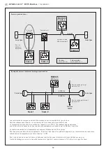
Page 34: ...it tre r parti en plusieurs segments par l interm diaire de repeaters L adresse des correspondants peut tre fix e de 1 247 Pour la ligne de bus on peut utiliser un c ble avec ligne de donn es alimenta...

Page 35: ...e r clamation les appareils ne sont repris que dans leur emballage d origine et si tous les l ments de l appareil sont complets La mise en service ne doit tre effectu e que par du personnel qualifi Av...

Page 36: ...Plug for display contact is on the right side DIP A Bus address DIP B Bus parameters Baud rate parity Telegram indicator Reception LED green Error LED red LED internal status Offset correction tempera...

Page 37: ...a F 0 85 ENT 20 80 C TP 0 50 C Modbus 1201 42B6 6001 005 RFTF MODBUS P LCD 5 x 1 x Modbus 1201 42B6 7001 005 RFTF MODBUS P 5L 5 x 1 x Modbus 1201 42B6 6119 005 RFTF MODBUS P 5L LCD 5 x 1 x Modbus 120...

Page 38: ...P 1 ON DIP 2 64 DIP 2 ON DIP 3 32 DIP 3 OFF DIP 4 16 DIP 4 OFF DIP 5 8 DIP 5 OFF DIP 6 4 DIP 6 OFF DIP 7 2 DIP 7 OFF DIP 8 1 DIP 8 ON 128 64 1 193 Modbus DIP 1 DIP 2 MODBUS DIP B 9600 ON OFF 1 2 3 4 5...

Page 39: ...1 C 7 14 4x0001 10 4 0002 4 0012 4x0001 0 7 4x0005 0 A 1 B 2 C 3 D 4 DP 5 6 7 8 9 10 11 12 13 14 15 A A B C D E F G B C D DP 14 1 14 2 14 4x0003 4x0004 0 A 1 B 2 C 3 D 4 E 5 F 6 G 7 G 8 H 9 I 10 J 11...

Page 40: ...V 87 W 88 X 89 Y 90 Z 91 93 ASCII 94 95 _ 96 97 a 98 b 99 c 100 d 101 e 102 f 103 g 104 h 105 i 106 j 107 k 108 l 109 m 110 n 111 o 112 p 113 q ASCII 114 r 115 s 116 t 117 u 118 v 119 w 120 x 121 y 12...

Page 41: ...1 1x0002 1 1x0003 MODBUS Function 02 Read Discrete Input 1 LED Mode 5 05 Write Single Coil 1x0001 1x0002 1x0003 05 Write Single Coil Bit 6 04 Read Input Register 3x0001 4 16 0 500 0 0 50 0 C 3x0002 32...

Page 42: ...4x0004 14 2 16 4x0005 16 4x0006 8 0 255 ASCII 4x0007 8 0 255 ASCII 4x0008 8 0 255 ASCII 4x0009 D 8 0 255 ASCII 4x0010 8 0 255 ASCII 4x0011 F 8 0 255 ASCII 4x0012 G 8 0 255 ASCII 4x0040 8 Bit 0 63 0 1...

Page 43: ...3 4 8 0 100 Default 0 4x0024 5 8 0 100 Default 0 0 9 0 9 10 19 10 19 20 29 20 29 30 39 30 39 40 49 40 49 50 59 50 19 60 69 60 69 70 79 70 79 80 89 80 89 100 4x0025 1 0 63 4x0026 1 0 63 4x0027 1 0 63 4...

Page 44: ...0 1 CLEAR SET 0x0007 6 0 1 OFF ON 02 Read Discrete Input 1x0001 0 0 1 OFF ON 1x0002 1 0 1 OFF ON 1x0003 2 0 1 OFF ON 1x0003 1x0008 0 08 Diagnostics 00 Loopback 01 Modbus Reset Listen Only Mode 04 List...

Page 45: ...45 DIP 6 Modbus Modbus 32 1 247 100 Profibus Slave n MODBUS RTU Master RS 485 20 n 40 n Slave 1 Slave 2 LA LA A D1 D 5 B GND B D0 D MODBUS RTU Master Slave 1 Slave 2 r AERASGARD RFTF Modbus...

Page 46: ...46 r ZVEI VDE EMV EMV VDE VDI DDC PLC 0 5 g r...

Page 47: ...at date of publication They are only meant to inform about our products and their application potential but do not imply any warranty as to certain product characteristics Since the devices are used u...

Page 48: ...120 0 1 1 1 1 0 0 0 121 0 1 1 1 1 0 0 1 122 0 1 1 1 1 0 1 0 123 0 1 1 1 1 0 1 1 124 0 1 1 1 1 1 0 0 125 0 1 1 1 1 1 0 1 126 0 1 1 1 1 1 1 0 127 0 1 1 1 1 1 1 1 128 1 0 0 0 0 0 0 0 129 1 0 0 0 0 0 0 1...

Reviews: