G
HYGRASREG
®
RH - 30
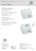
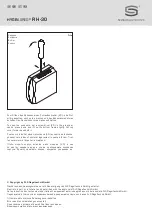
Electronic room hygrostats and humidity sensors HYGRASREG
®
RH-30 with one continuous and two switching outputs, adjustable switching
thresholds, optional with or without display indicating the actual humidity, accuracy class ± 3 % r. H. They are used to control and monitor
the relative humidity, e.g. in venti lation and air conditioning ducts, laboratories, production facilities, climatic test cabinets, indoor swimming pools,
greenhouses, etc. to control humidifying and dehumidifying equipment. These measuring transducers are designed for exact humidity measurement.
HYGRASREG
®
RH-30 uses a digital long-term stable sensor as measuring element for humidity measurement. Applications in dust-free,
pollutant-free, non-aggressive air.
TECHNICAL DATA:
Power supply: ........................ 24 V AC ⁄ DC (optional 230 V AC via external power supply unit)
Power consumption: ................ < 2 VA ⁄ 24 V DC
Setting range: ....................... 5 … 95 % r. H. (switch steps 1 and 2 are separately adjustable)
Operating difference: ............... Mode 1: both switch steps are arbitrary adjustable
Mode 2: 5 % between both switch steps
Output: ................................. potential-free changeover contacts (2 x changeover contact 24 V,
separately adjustable, 1x 0 - 10 V ^= 0 - 100 % r. H.)
Sensors: ............................... digital humidity sensor
Deviation, humidity: .................
± 3 % r. H.
(20…90 %); at + 20 °C, otherwise ± 5 % r. H.
Long-term stability:................. ± 1 % per year
Hysteresis: ............................ max. 3 % r. H.
Enclosure: ............................. plastic, material ABS,
colour pure white (similar RAL 9010)
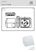
Enclosure dimensions: ............. 98 x 106 x 34 mm (Frija II)
Installation: ........................... wall mounting or on in-wall flush box, Ø 55 mm, base with 4-hole for mounting on vertically or
horizontally installed in-wall flush boxes for cable entry from the back, with predetermined breaking point
for on - wall cable entry from top ⁄ bottom in case of plain on - wall installation
Protection class: .................... III (according to EN 60 730)
Protection type: ..................... IP 20 (according to EN 60 529)
Electrical connection: ............. 0.14 - 2.5 mm
2
, via terminal screws
Standards: ............................ CE conformity, EMC directive 2004 ⁄ 108 ⁄ EC
Optional: ............................... Single-line display, shifting, 36 x15 mm (W x H), for displaying ACTUAL humidity respectively
for humidity setpoint adjustment
FUNCTION:
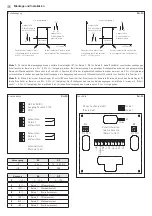
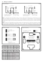
Humidifying: ..............................
1
st
step:
wire contacts 4 - 5.
When actual humidity falls more than 3 % r. H. (hysteresis)
below switching threshold S1, changeover contact switches to 4 - 5.
2
nd
step:
wire contacts 7 - 8.
When actual humidity falls more than 3 % r. H. (hysteresis)
below switching threshold S 2, changeover contact switches to 7 - 8.
Terminal 2: 1x 0 - 10 V equivalent to 0…100 % r. H.
Dehumidifying: ..........................
1
st
step:
wire contacts 5 - 6.
When actual humidity exceeds switching threshold S 1,
changeover contact switches to 5 - 6.
2
nd
step:
wire contacts 8 - 9.
When actual humidity exceeds switching threshold S 2,
changeover contact switches to 8 - 9. Terminal 2: 1x 0 - 10 V ^
= 0 - 100 % r. H.
Type ⁄ WG2
Setting Range
Humidity
Output
Steps Display Item No.
RH - 30
External setting
RH - 3 0 W
5 … 95 % r. H.
2 x Changeover contact, 1x 0 -10 V
two-step
1202-3046-1011-000
RH - 3 0 W_ DISP L AY
5 … 95 % r. H.
2 x Changeover contact, 1x 0 -10 V
two-step
■
1202-3046-1111-000
RH - 30 - U
Internal setting
RH - 3 0 W U
5 … 95 % r. H.
2 x Changeover contact, 1x 0 -10 V
two-step
1202-3046-1021-000
Summary of Contents for HYGRASREG RH-30
Page 16: ...HYGRASREG RH 30 D G F r...

