background image

THERM

ASREG

®

  FM 020

THERMASREG

®

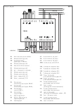
 FM 020 is a communicative built-in controller for temperature control of climate control convectors, or heating or venti-

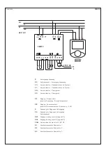
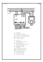
lation devices. It is provided with four analog outputs, four digital inputs (presence, window contact, party button, two-pipe system moni-
toring), and four digital outputs (assignment schedule see datasheet). It can either be operated independently, or in connection with a 
 superior control device (SPS  ⁄  DDC or Soft SPS), a building management system (e.g. RcWare Vision), or another monitoring, control and 
data acquisition system being applicable as Modbus master. For manual intervention and room temperature measurement, an analog 
room unit is used, for example our RTF_PT1000_D5.

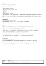
TECHNICAL DATA:

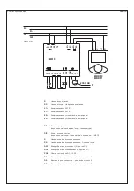
Power consumption: .................. 24 V AC  (± 10 %)

700 mVA + peripheral devices  (ca. 5 VA)

Inputs:........................................... 4 x DI  for one potential-free contact,

24 V AC, 15 mA  (presence, window contact,  
changeover switch, party mode) 


4 x AI 20...1600 ohm  (room temperature, setpoint,  
ventilator step, reserve) 

Outputs: ....................................... 2 x semiconductor relay for AC load, zero switching, 

24 V AC, max. switching current 0.4 A 


2 x two-way thyristors (TRIAC),  
24 V AC, max. switching current 0.4 A,  
recommended thermal actuators are  
Siemens STA71, Danfoss TWA (24 V types)


3 x relay 230 V ⁄ 5 A (3 ventilator steps)


2 x AO  0 ...10 V, max. output current 10 mA,  
short circuit current limitation to 20 mA.

Load (analog outputs): ............... 10 kOhm, max. current 10 mA, 

outputs short-circuit proof, limited to 20 mA

Communication: .......................... with room devices: 

RS485 – Modbus RTU, 9600, N, 8, 1, master


with the building management system:  
RS485 – Modbus RTU, 9600, N, 8, 1, slave

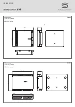
Dimensions: ................................. 113 x 90 x 24 mm  (with retainer)
Electrical connection:  ............... 0.14  -  1.5 mm

2

  via screw terminals

Installation: .................................. by 2 screws, DIN top hat rail adapter optional
Protection class: ........................ II  (according to EN 60 730)
Protection type:.......................... IP 20  (according to EN 60 529)
Standards: ................................... CE conformity, electromagnetic compatibility according to EN 61 326 + A1 + A2, 

EMC directive 89 ⁄ 336 ⁄ EEC, low-voltage directive 73 ⁄ 23 ⁄ EEC

FUNCTION:

The controller communicates with an analog room unit (which comprises a Pt1000 temperature sensor, setpoint adjustment, and ventila-
tor steps  switching) in rooms, for which UI... room devices with display are not applicable. 
Alternatively (not available in this firmware version), a communicative room device can be used via an assigned bus (K2+, K2-). The room 
unit detects the room temperature. Setpoint adjustment via turning knob and taking over of default control signal into the operating mode 
by shortly pressing the knob, or via the menu. The room temperature is measured in the range form – 20 °C to + 50 °C. 
The detected and the input values are processed by a PI-algorithm. At the output, 0...10 V signals for analog actuators as well as pulse 
width modulated 24 V AC signals for two-way thyristors (PWM TRIAC) for activating thermal actuators are output.  
These  controllers  are  intended  for  operation  in  a  normal  and  chemically  non-aggressive  environment.  They  do  not  require  any  mainte-
nance or servicing. They are mounted with two screws to a flat surface, e.g. on the fan coil convector body, or on an installation plate. The 
retainers can be removed and an optionally available DIN top hat rail adapter can be attached at the bottom of the controller. 
The controller includes a real-time clock with a week programme time switch (6 switching events per day). That switches over between  
3 operating modes: normal temperature, temperature setback, and OFF. The controller has two digital inputs, one for a presence detec-
tor (access card reader,  passive infrared sensor, etc.) and one for a window contact or dew point sensor (switches to OFF). Both contacts 
can be used as breaker or normally open contacts. The selection is made via configuration software. 
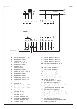
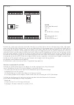
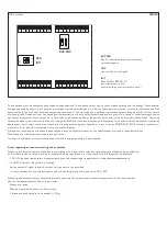
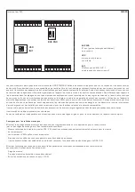
Three LEDs indicate correct functioning: 
Green (PWR) fan power supply OK 
Red  (TX1) – data transmission to the building automation bus 
Red  (TX2) – data transmission to the room unit 
Inside on the circuit board are four DIP switches: 
2  x  K1 Bus End, Reserve, and INIT to set the ex-factory default settings. 
The controller communicates with the central building control system via a RS485 bus with Modbus RTU and therefore, can be applied in 
connection  with  various  control  systems.  See  variables  list  (Modbus  table)  in  the  separate  document  Room  devices  and  Controllers, 
transmission protocol. Another bus K2 communicates with the room unit. Configuration software is used for configuration and commis-
sioning of this device, which can be downloaded at www.spluss.de free of charge.

Summary of Contents for THERMASREG FM Series

Page 1: ...makonvektoren Heiz und Klimager te G Operating Instructions Mounting Installation Field bus module Modbus for fan coil convectors climate control convectors heating and air conditioning units F Notice...

Page 2: ...THERMASREG FM D G F r Ma zeichnung FM010 Dimensional drawing Plan cot Ma zeichnung FM020 Dimensional drawing Plan cot 94 1 23 4 82 8 29 0 114 0 90 5...

Page 3: ...lsbreitenmodulierte Zweiweg Thyristoren PWM TRIAC zur Ansteuerung der Thermoventile Diese Regler sind zum Betrieb in einer normalen und chemisch nicht aggressiven Umgebung vorgesehen Sie bed rfen kein...

Page 4: ...ensterkontakt schaltet Normaltemperatur Absenkung AUS G Spannung f r Eing nge und Ausg nge G0 Spannung f r Eing nge und Ausg nge Referenzpunkt DO1 Ausgang Heizungsventil G gegen G0 DO2 Ausgang K hlung...

Page 5: ...nicht in dieser Firmware Version erh ltlich kann ein kommunikatives Raumger t ber einen zugeordneten Bus K2 K2 verwendet werden Das Raumger t erfasst die Raumtemperatur Sollwert Einstellung mittels D...

Page 6: ...le Eing nge die an 24 V AC der G G0 Spannung betrieben werden Eingang Anwesenheit schaltet Normaltemperatur Tag Absenkung Nacht Eingang Fensterkontakt schaltet auf AUS Absenkung wenn das Fenster offen...

Page 7: ...tor Relaisstufe 2 Q3 Ventilatorkonvektor Relaisstufe 3 COM Gemeinsamer Kontakt f r Q1 Q2 Q3 DO4 Halbleiterrelais Ausgang DO4 C4 Halbleiterrelais Ausgang DO4 DO5 Halbleiterrelais Ausgang DO5 C5 Halblei...

Page 8: ...ht den EMV Richt linien entsprechen kann zur Beeinflussung der Funktionsweise f hren Dieses Ger t darf nicht f r berwachungszwecke welche ausschlie lich dem Schutz von Personen gegen Gef hrdung oder V...

Page 9: ...er Produkte m glich Bei Ver nderungen der Ger te durch den Anwender entfallen alle Gew hrleistungsanspr che Dieses Ger t darf nicht in der N he von W rmequellen z B Heizk rpern oder deren W rmestrom e...

Page 10: ...d by a PI algorithm at the output of which pulse width modulated two way thyristors PWM TRIAC for activating the thermovalves are installed These controllers are intended for operation in a normal and...

Page 11: ...DI2 Input window contact switches normal temperature setback OFF G Voltage for inputs and outputs G0 Voltage for inputs and outputs reference point DO1 Output heating valve G against G0 DO2 Output coo...

Page 12: ...m devices with display are not applicable Alternatively not available in this firmware version a communicative room device can be used via an assigned bus K2 K2 The room unit detects the room temperat...

Page 13: ...e digital inputs which are operated at 24 V AC the G G0 voltage Input presence switches to normal temperature daytime setback nighttime Input window contact switches to OFF setback when window is open...

Page 14: ...ep 1 Q2 Fan coil convector relay step 2 Q3 Fan coil convector relay step 3 COM Common contact for Q1 Q2 Q3 DO4 Semiconductor relay output DO4 C4 Semiconductor relay output DO4 DO5 Semiconductor relay...

Page 15: ...MERGENCY STOP switch for systems or machinery or for any other comparable safety relevant purposes Dimensions of enclosures or enclosure accessories may show slight tolerances on the specifications pr...

Page 16: ...s and continuous improvement of our products In case of any modifications made by the user all warranty claims are forfeited This device must not be installed close to heat sources e g radiators or be...

Page 17: ...impulsion MLI triac pour la commande des vannes thermiques Ces r gulateurs sont con us pour une exploitation en environnement normal et chimiquement non agressif Ils ne n cessitent aucun entretien ni...

Page 18: ...male DI2 entr e contact fen tre commute la temp rature normale l abaissement ARR T G tension pour entr es et sorties G0 tension pour entr es et sorties point de r f rence DO1 sortie vanne de chauffage...

Page 19: ...tiliser un appareil d ambiance communiquant via un bus attri bu K2 K2 L appareil d ambiance mesure la temp rature ambiante Pour r gler la valeur de consigne utilisez le bouton rotatif et appuyez bri v...

Page 20: ...es num riques libres de potentiel aliment es en 24 V ca de la tension G G0 entr e pr sence commute la temp rature normale jour l abaissement nuit entr e contact fen tre commute sur ARR T abaissement s...

Page 21: ...du ventilo convecteur Q2 niveau relais 2 du ventilo convecteur Q3 niveau relais 3 du ventilo convecteur COM contact commun pour Q1 Q2 Q3 DO4 sortie relais semi conducteur DO4 C4 sortie relais semi co...

Page 22: ...tection des personnes contre les dangers ou les blessures ni comme interrupteur d arr t d urgence sur des installations ou des machines ni pour des fonctions relatives la s curit comparables Il est po...

Page 23: ...ion continue de nos produits En cas de modifications des appareils par l utilisateur tous droits de garantie ne seront pas reconnus Cet appareil ne doit pas tre utilis proximit des sources de chaleur...

Page 24: ...STA71 Danfoss TWA 24 230 5 A RS485 Modbus RTU 9600 N 8 1 Master RS485 Modbus RTU 9600 N 8 1 Slave 75 x 90 x 24 104 x 90 x 24 0 14 1 5 2 DIN II EN 60730 IP 20 EN 60529 CE EN 61326 A1 A2 89 336 EEC 73...

Page 25: ...M010 G G0 K1 K1 K2 K2 DI1 DI2 G G0 DO1 G G0 DO2 G G0 COM Q1 Q2 Q3 Q1 1 Q2 2 Q3 3 G G0 FM010 DI2 DI1 G G G0 G0 DO2 DO1 COM Q3 Q2 Q1 N L 6 7 4 3 K K MBR010 MBR011 24 V AC 230 V AC G TE G0 G0 G K1 K1 K2...

Page 26: ...1 Danfoss TWA 24 230 5 A 3 2 AO 0 10 10 20 10 10 20 RS485 Modbus RTU 9600 N 8 1 Master RS485 Modbus RTU 9600 N 8 1 Slave 113 x 90 x 24 0 14 1 5 2 DIN II EN 60730 IP 20 EN 60529 CE EN 61 326 A1 A2 89 3...

Page 27: ...1 FM020 Fieldbus Modbus Pt1000 0 500 500 Off 100 1 180 2 270 3 390 Pt1000 1500 0 K 0 500 3 5 3 5 K 0 10 0 10 GO 24 24 D01 D02 24 G G0 2 PI 1 3 1 D04 D05 Modbus Modbus...

Page 28: ...2 RS485 G 24 V AC G0 24V AC TE Q1 1 Q2 2 Q3 3 COM Q1 Q2 Q3 DO4 DO4 C4 DO4 DO5 DO5 C5 DO5 DO1 G G0 DO2 G G0 G0 DI1 G0 DI2 DI3 G0 DI4 K1 K1 K2 K2 G0 G TE AO2 AO1 G0 G0 G0 G0 G0 AI4 AI3 AI2 AI1 COM Q3 Q2...

Page 29: ...Geb udeleittechnik endet hier USR Benutzer Schalter nicht belegt INIT setzt COM auf 9600 N 8 1 und die Adresse im Geb udeleittechnik Bus auf 1 EMV VDE VDI DDC PLC 0 5 G BUS END K1 Bus Geb udeleittech...

Page 30: ...ZVEI VDE EMV VDE r...

Page 31: ...niques Copyright by S S Regeltechnik GmbH Nachdruck auch auszugsweise nur mit Genehmigung von S S Regeltechnik GmbH gestattet Reprints in part or in total are only permitted with the approval of S S R...

Page 32: ...THERMASREG FM D G F r...

Reviews: