background image

Our “General Terms and Conditions for Business“ together with the “General Conditions for the Supply of Products and Services of the Electrical 
and Electronics Industry“ (ZVEI conditions) including supplementary clause “Extended Retention of Title“ apply as the exclusive terms and conditions.

In additionIn addition, the following points are to be observed:
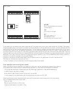
–  These instructions must be read before installation and putting in operation and all notes provided therein are to be  regarded!
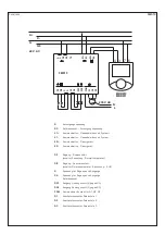
–  Devices must only be connected to safety extra-low voltage and under dead-voltage condition. To avoid damages and errors the device 

(e.g. by voltage induction) shielded cables are to be used, laying parallel with current-carrying lines is to be avoided, and EMC directives are to 
be observed.

–  This device shall only be used for its intended purpose. Respective safety regulations issued by the VDE, the states, their  control authorities, 

the TÜV and the local energy supply company must be observed. The purchaser has to adhere to the building and safety regulations and has to 
prevent perils of any kind.

–  No warranties or liabilities will be assumed for defects and damages arising from improper use of this device.
–  Consequential damages caused by a fault in this device are excluded from warranty or liability.
–  These devices must be installed by authorised specialists only.
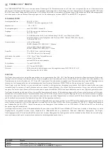
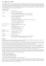
–  The technical data and connecting conditions of the mounting and operating instructions delivered together with the device are exclusively 

valid. Deviations from the catalogue representation are not explicitly mentioned and are possible in terms of technical progress and continuous 
improvement of our products.

–  In case of any modifications made by the user, all warranty claims are forfeited.
–  This device must not be installed close to heat sources (e.g. radiators) or be exposed to their heat flow. Direct sun irradiation or heat 

 irradiation by similar sources (powerful lamps, halogen spotlights) must absolutely be avoided.

–  Operating this device close to other devices that do not comply with EMC directives may influence functionality.
–  This device must not be used for monitoring applications, which solely serve the purpose of protecting persons against hazards or injury, 

or as an EMERGENCY STOP switch for systems or machinery, or for any other similar safety-relevant purposes.

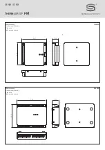
–  Dimensions of enclosures or enclosure accessories may show slight tolerances on the specifications provided in these instructions.
–  Modifications of these records are not permitted.
–  In case of a complaint, only complete devices returned in original packing will be accepted.

These instructions must be read before installation and putting in operation and all notes provided therein are to be regarded! 
To avoid damages  ⁄  errors, preferably shielded cables shall be used.  
Laying parallel with current-carrying lines must absolutely be avoided. The EMC directives must be adhered to. 

These devices shall only be used for their intended purpose. Respective safety regulations issued by the VDE, the states, their control authorities, 
the TÜV and the local energy supply company must be observed. The buyer has to adhere to the building and safety regulations and has to prevent all 
perils of any kind. We will not assume any warranties or liabilities whatsoever for defects and damages arising from improper use of these  devices. 
These devices must be installed by authorized qualified personnel only. 

G  

General notes

Summary of Contents for THERMASREG FM Series

Page 1: ...makonvektoren Heiz und Klimager te G Operating Instructions Mounting Installation Field bus module Modbus for fan coil convectors climate control convectors heating and air conditioning units F Notice...

Page 2: ...THERMASREG FM D G F r Ma zeichnung FM010 Dimensional drawing Plan cot Ma zeichnung FM020 Dimensional drawing Plan cot 94 1 23 4 82 8 29 0 114 0 90 5...

Page 3: ...lsbreitenmodulierte Zweiweg Thyristoren PWM TRIAC zur Ansteuerung der Thermoventile Diese Regler sind zum Betrieb in einer normalen und chemisch nicht aggressiven Umgebung vorgesehen Sie bed rfen kein...

Page 4: ...ensterkontakt schaltet Normaltemperatur Absenkung AUS G Spannung f r Eing nge und Ausg nge G0 Spannung f r Eing nge und Ausg nge Referenzpunkt DO1 Ausgang Heizungsventil G gegen G0 DO2 Ausgang K hlung...

Page 5: ...nicht in dieser Firmware Version erh ltlich kann ein kommunikatives Raumger t ber einen zugeordneten Bus K2 K2 verwendet werden Das Raumger t erfasst die Raumtemperatur Sollwert Einstellung mittels D...

Page 6: ...le Eing nge die an 24 V AC der G G0 Spannung betrieben werden Eingang Anwesenheit schaltet Normaltemperatur Tag Absenkung Nacht Eingang Fensterkontakt schaltet auf AUS Absenkung wenn das Fenster offen...

Page 7: ...tor Relaisstufe 2 Q3 Ventilatorkonvektor Relaisstufe 3 COM Gemeinsamer Kontakt f r Q1 Q2 Q3 DO4 Halbleiterrelais Ausgang DO4 C4 Halbleiterrelais Ausgang DO4 DO5 Halbleiterrelais Ausgang DO5 C5 Halblei...

Page 8: ...ht den EMV Richt linien entsprechen kann zur Beeinflussung der Funktionsweise f hren Dieses Ger t darf nicht f r berwachungszwecke welche ausschlie lich dem Schutz von Personen gegen Gef hrdung oder V...

Page 9: ...er Produkte m glich Bei Ver nderungen der Ger te durch den Anwender entfallen alle Gew hrleistungsanspr che Dieses Ger t darf nicht in der N he von W rmequellen z B Heizk rpern oder deren W rmestrom e...

Page 10: ...d by a PI algorithm at the output of which pulse width modulated two way thyristors PWM TRIAC for activating the thermovalves are installed These controllers are intended for operation in a normal and...

Page 11: ...DI2 Input window contact switches normal temperature setback OFF G Voltage for inputs and outputs G0 Voltage for inputs and outputs reference point DO1 Output heating valve G against G0 DO2 Output coo...

Page 12: ...m devices with display are not applicable Alternatively not available in this firmware version a communicative room device can be used via an assigned bus K2 K2 The room unit detects the room temperat...

Page 13: ...e digital inputs which are operated at 24 V AC the G G0 voltage Input presence switches to normal temperature daytime setback nighttime Input window contact switches to OFF setback when window is open...

Page 14: ...ep 1 Q2 Fan coil convector relay step 2 Q3 Fan coil convector relay step 3 COM Common contact for Q1 Q2 Q3 DO4 Semiconductor relay output DO4 C4 Semiconductor relay output DO4 DO5 Semiconductor relay...

Page 15: ...MERGENCY STOP switch for systems or machinery or for any other comparable safety relevant purposes Dimensions of enclosures or enclosure accessories may show slight tolerances on the specifications pr...

Page 16: ...s and continuous improvement of our products In case of any modifications made by the user all warranty claims are forfeited This device must not be installed close to heat sources e g radiators or be...

Page 17: ...impulsion MLI triac pour la commande des vannes thermiques Ces r gulateurs sont con us pour une exploitation en environnement normal et chimiquement non agressif Ils ne n cessitent aucun entretien ni...

Page 18: ...male DI2 entr e contact fen tre commute la temp rature normale l abaissement ARR T G tension pour entr es et sorties G0 tension pour entr es et sorties point de r f rence DO1 sortie vanne de chauffage...

Page 19: ...tiliser un appareil d ambiance communiquant via un bus attri bu K2 K2 L appareil d ambiance mesure la temp rature ambiante Pour r gler la valeur de consigne utilisez le bouton rotatif et appuyez bri v...

Page 20: ...es num riques libres de potentiel aliment es en 24 V ca de la tension G G0 entr e pr sence commute la temp rature normale jour l abaissement nuit entr e contact fen tre commute sur ARR T abaissement s...

Page 21: ...du ventilo convecteur Q2 niveau relais 2 du ventilo convecteur Q3 niveau relais 3 du ventilo convecteur COM contact commun pour Q1 Q2 Q3 DO4 sortie relais semi conducteur DO4 C4 sortie relais semi co...

Page 22: ...tection des personnes contre les dangers ou les blessures ni comme interrupteur d arr t d urgence sur des installations ou des machines ni pour des fonctions relatives la s curit comparables Il est po...

Page 23: ...ion continue de nos produits En cas de modifications des appareils par l utilisateur tous droits de garantie ne seront pas reconnus Cet appareil ne doit pas tre utilis proximit des sources de chaleur...

Page 24: ...STA71 Danfoss TWA 24 230 5 A RS485 Modbus RTU 9600 N 8 1 Master RS485 Modbus RTU 9600 N 8 1 Slave 75 x 90 x 24 104 x 90 x 24 0 14 1 5 2 DIN II EN 60730 IP 20 EN 60529 CE EN 61326 A1 A2 89 336 EEC 73...

Page 25: ...M010 G G0 K1 K1 K2 K2 DI1 DI2 G G0 DO1 G G0 DO2 G G0 COM Q1 Q2 Q3 Q1 1 Q2 2 Q3 3 G G0 FM010 DI2 DI1 G G G0 G0 DO2 DO1 COM Q3 Q2 Q1 N L 6 7 4 3 K K MBR010 MBR011 24 V AC 230 V AC G TE G0 G0 G K1 K1 K2...

Page 26: ...1 Danfoss TWA 24 230 5 A 3 2 AO 0 10 10 20 10 10 20 RS485 Modbus RTU 9600 N 8 1 Master RS485 Modbus RTU 9600 N 8 1 Slave 113 x 90 x 24 0 14 1 5 2 DIN II EN 60730 IP 20 EN 60529 CE EN 61 326 A1 A2 89 3...

Page 27: ...1 FM020 Fieldbus Modbus Pt1000 0 500 500 Off 100 1 180 2 270 3 390 Pt1000 1500 0 K 0 500 3 5 3 5 K 0 10 0 10 GO 24 24 D01 D02 24 G G0 2 PI 1 3 1 D04 D05 Modbus Modbus...

Page 28: ...2 RS485 G 24 V AC G0 24V AC TE Q1 1 Q2 2 Q3 3 COM Q1 Q2 Q3 DO4 DO4 C4 DO4 DO5 DO5 C5 DO5 DO1 G G0 DO2 G G0 G0 DI1 G0 DI2 DI3 G0 DI4 K1 K1 K2 K2 G0 G TE AO2 AO1 G0 G0 G0 G0 G0 AI4 AI3 AI2 AI1 COM Q3 Q2...

Page 29: ...Geb udeleittechnik endet hier USR Benutzer Schalter nicht belegt INIT setzt COM auf 9600 N 8 1 und die Adresse im Geb udeleittechnik Bus auf 1 EMV VDE VDI DDC PLC 0 5 G BUS END K1 Bus Geb udeleittech...

Page 30: ...ZVEI VDE EMV VDE r...

Page 31: ...niques Copyright by S S Regeltechnik GmbH Nachdruck auch auszugsweise nur mit Genehmigung von S S Regeltechnik GmbH gestattet Reprints in part or in total are only permitted with the approval of S S R...

Page 32: ...THERMASREG FM D G F r...

Reviews: