
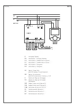
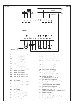

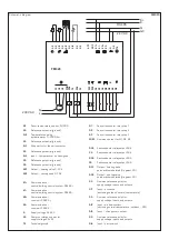
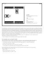

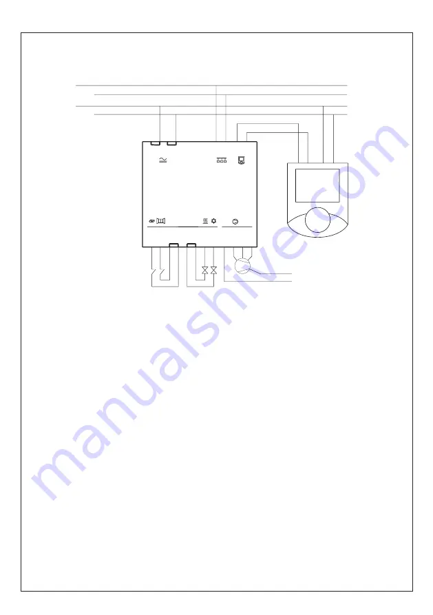
Schaltbild
FM 010
G
Versorgungsspannung
G0
Referenzpunkt – Versorgungsspannung
K1+
Kommunikation – Gebäudeleittechnik-
K1 –
Kommunikation – Gebäudeleittechnik-System –
K2+
Kommunikation – Raumgerät +
K2–
Kommunikation – Raumgerät –
DI1
Eingang – Anwesenheit
(schaltet Absenkung ⁄ Normaltemperatur)
DI2
Eingang – Fensterkontakt
(schaltet Normaltemperatur ⁄ Absenkung – AUS)
G
Spannung für Eingänge und Ausgänge
G0
Spannung für Eingänge und Ausgänge –
Referenzpunkt
DO1
Ausgang Heizungsventil (G, gegen G0)
DO2
Ausgang Kühlungsventil (G, gegen G0)
COM
Gemeinsamer Kontakt für Q1, Q2, Q3
Q1
Ventilatorkonvektor-Relaisstufe 1
Q2
Ventilatorkonvektor-Relaisstufe 2
Q3
Ventilatorkonvektor-Relaisstufe 3
G
G0
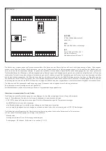
FM010
DI2
DI1
G
G
G0
G0
DO2
DO1
COM
Q3
Q2
Q1
N
L
6
7
4 3
K+
K-
MBR010
MBR011
24 V AC
230 V AC
G
TE
G0
G0
G
K1-
K1+
K2-
K2+
Summary of Contents for THERMASREG FM Series
Page 30: ...ZVEI VDE EMV VDE r...
Page 32: ...THERMASREG FM D G F r...


