5. Commissioning
Control unit mounted apart of the detector head:
Changes of the connection cables between the detector head GLS and the control unit
must be reconfirmed by S+S. Only original cables must be used
otherwise the CE-certification become unvalid.
The connections cable must be installed separate from other power and control lines
and carefully fixed or layed into a cable duct.
Installation of more then one GLS-coil:
In case that two or more GLS-coils are working in adjacent lines interferences can occur.
Therefore you need to reconfirm S+S.
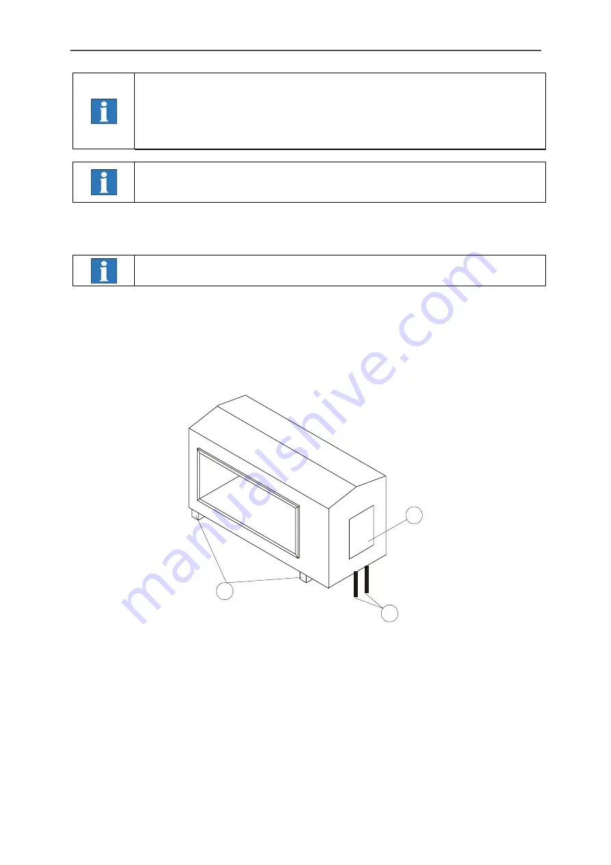
Pay attention to the following order when mounting the GLS to conveying pipe:
Do not remove the plastic bars or replace them by other materials. This parts are not
only used as fastening elements but also as an electrical insulator.
1. If necessary disconnect the connection cable (3) (see also 5.2).
2. Put the belt and sliding board through the detector opening. Fasten the board and make sure that
neither the sliding board nor the belt touches the shaft walls inside of the detector opening.
3. For mounting the detector head use only the plastic bars.
4. Connect connector cable (3) according to picture 5.2.
1
2
3
13