5. Commissioning
5.2 Connections
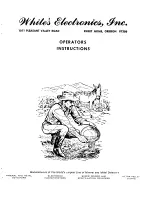
If the connection cable between detector head and control unit has been removed reconnect it accord-
ing to the sketch:
5.2.1 Control Unit PRIMUS / SENSITY
Electrical work should only be carried out by qualified personnel.
Before removing cover plates etc make sure the equipment is isolated from mains or
external voltage.
GLS metal detector
Coil connection boxes
Housing Control Unit
PRIMUS / SENSITY
Triax-Cable
1
1
T
ra
ns
m
itte
r
R
e
ce
iv
e
r
Receiver
Transmitter
1 2 3 4
5 6 7 8
9
9
9
9
Terminal coil connection box
Connector receiver
Connector transmitter
1
-----
1 white / brown
2 white / brown
2 2 x black (shield inside)
3 2 x black (shield inside)
3 yellow
4 yellow
4 green
5 green
5 -----
6 transparent
1 transparent
7 blue
2 blue
8 -----
3 -----
9 shield
outside
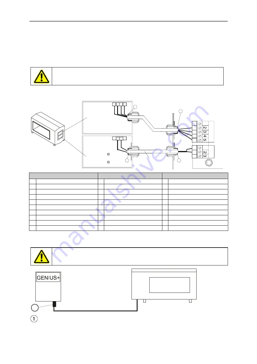
5.2.2 Control Unit
Electrical work should only be carried out by qualified personnel.
Before removing cover plates etc make sure the equipment is isolated from mains or ex-
ternal voltage.
GLS
1
Connector
The connection cable for control unit and detector head can be plugged.
14