


8
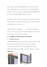
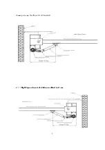
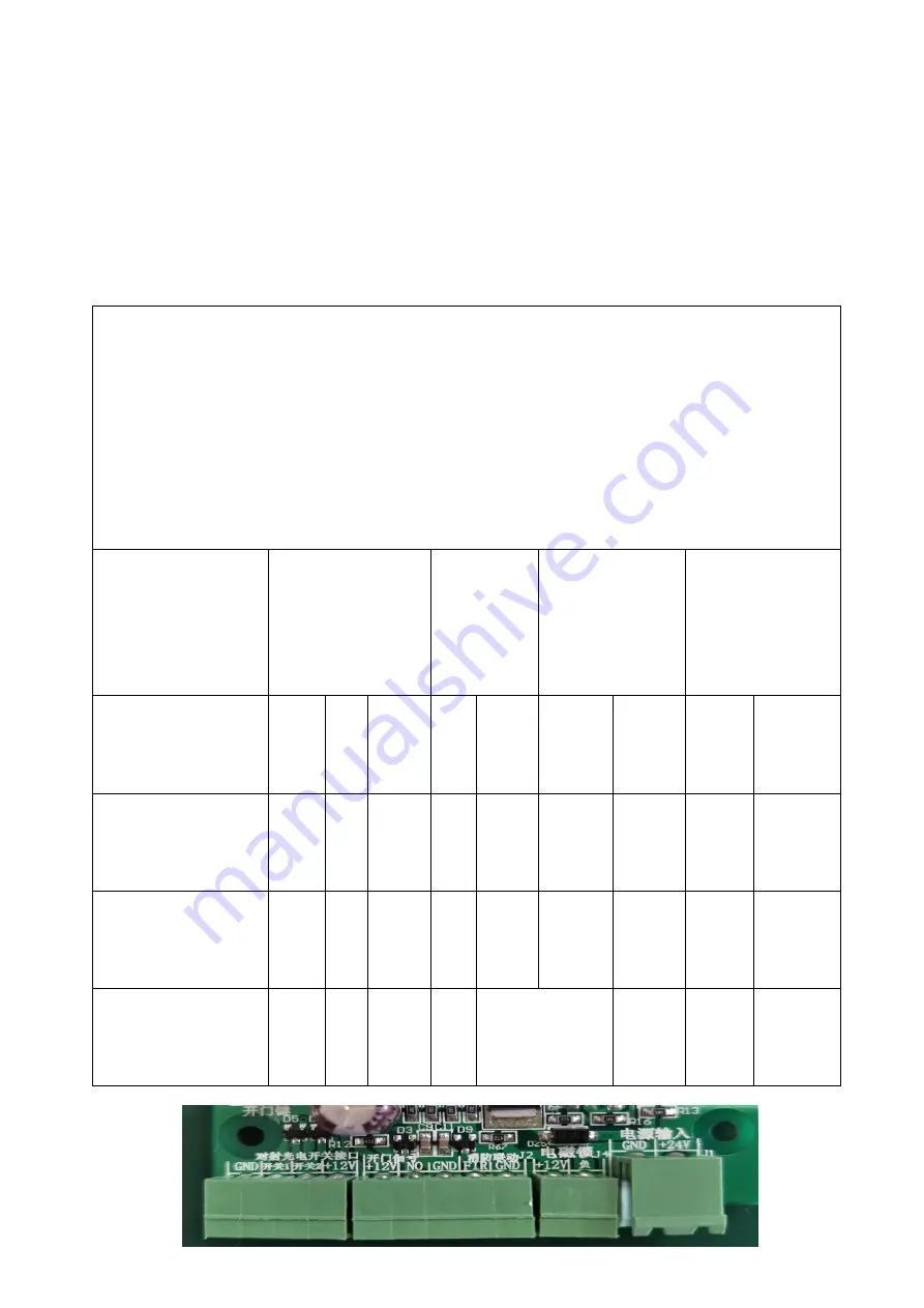
2.2 Connection of electrical part of door opener
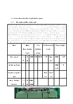
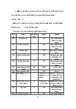
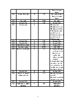
2.2.1 Description of the control port:
Warning: A. When the electrical part is connected, live work is strictly prohibited. Power
can be energized after all connections .
B. Do not connect the positive and negative
poles of the power supply inverse, otherwise the equipment will be damaged. Note:
A. Please
choose an electromagnetic lock whith supply voltage is 12V DC and the power ≤9W or our company's
electromagnetic lock. Otherwise it will cause abnormal operation or circuit damage.
B:
When leaving factory, the motor wire has been connected, do not take it out without any special
case.
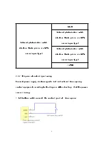
C: Opening signal of external access control equipment :
a: When the access
control equipment is the output of switch quantity (dry contact), the close switch controls
the opening of the door, and the switch should be open usually, without polarity requirements.
b: When voltage output (wet contact), add transfer module.
Name
Open
Door Control
Signal
Fire
fighting
linkage
Electromagn-et
ic lock
Power Supply
door opener
+12
V
N
O
GND FIR GND +12V Neg-a
tive
GND
+24V
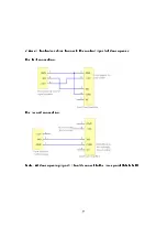
Switchi-ng Power
COM
or-V
+V
Electro-m agneti-c
Lock
Red
line
black
line
Access Control
Machine
+12
V
N
O
COM
GND


