background image

3 Connections of the BB35

extremely simple.Only two connections need to be made; mains power and audio signal.
A Stage Control connection is not neccesary for the functioning of the Blue box

Because all the components of a Blue Box are contained in a single cabinet, connection is

3.1

Mains Power Connection

voltage is configured at the factory according to standard used in the country of destination. The

The BB35 is internally selectable for 110-120/220-240V 50/60Hz mains voltage. The mains

exact voltages are stated at the frontpanel of the PMS6000. Switching between mains voltages
needs to done by selecting a jumper between position X1 and X3 on PCB BB3501.
Connecting to the wrong voltage is dangerous and may damage the PMS6000. Always ensure
that you use a correctly grounded power supply.
It is advisable to connect each unit seperately to the nearest main power supply socket.
The maximum advice for linked Blue Boxes using the AC out link on a 16A mains supply is 2
units.

stage accompany

R

BB35 USER MANUAL

3-1

CONNECT

IONS

3.2

Audio Connections

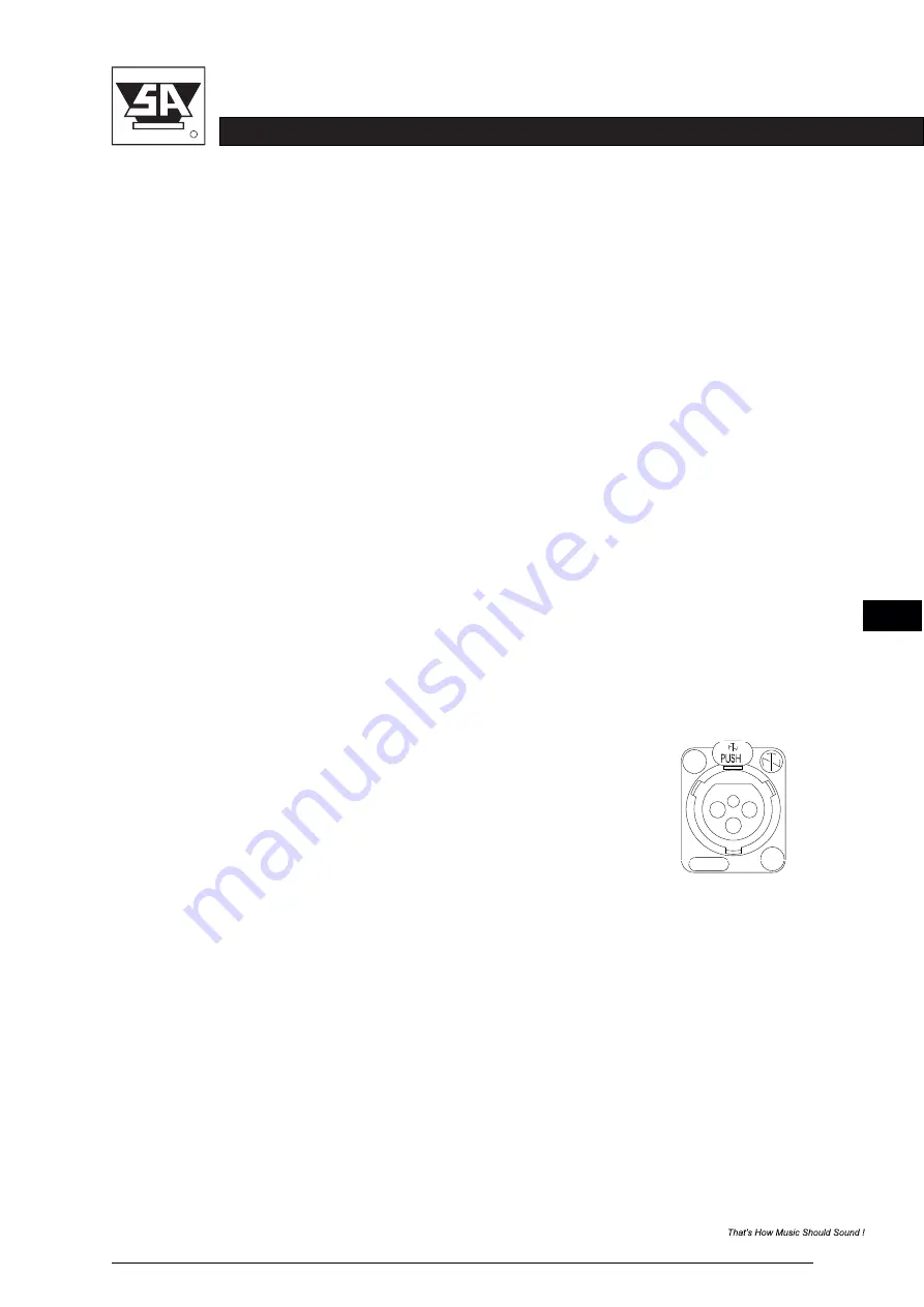
The XLR connectors (analog audio, AES/EBU  in and link) of the BB35 are wired as follows:

Pin 1

= shield

Pin 2

= normal phase ( or “hot”)

Pin 3

= inverted phase (signal- or “cold”)

Always use high quality XLR connectors and shielded signal cables. Using the signal link
connectors, up to 30 BB35s can be linked without a problem. If more than 30 BB35s need to
be interconnected, a separate signal driver should be used.

The input stages are electronically balanced. To make optimum use of the balanced input stages
even in unbalanced situations, use balanced signal cables and connect pin 3 to pin 1 at the
output of the preceding equipment. If this is not possible, connect pin 3 to pin 1 at the input of
the BB35.

NEUTRIK

+

+

1

2

3

The digital input of the BB35 offers two input channels on one electronically balanced XLR-
connector and will accept AES/EBU and S/PDIF input signals of 16 to 24 bit 44.1, 48, 88.2 or
96kHz. Use the control panel or Stage Control to select reproducing left or right channel.

Summary of Contents for Blue Box BB35

Page 1: ...Blue Box BB35 User Manual Version 1 0 Self Powered Loudspeaker Cabinet stage accompany R BB35 USER MANUAL ...

Page 2: ...n The Netherlands This manual is intended to provide information about the Stage Accompany BB35 Every effort has been made to make this manual complete and as accurate as possible However no warranty of suitability purpose or fitness is implied The information is provided on an as is basis Stage Accompany shall have neither liability nor responsibility to any person or identity with respect to any...

Page 3: ...stage accompany R BB35 USER MANUAL Table of Contents Quick Introduction to the BB35 Introduction Connections Operation Stage Control Recommendations Technical Specifications Warranty Overview ...

Page 4: ...4 2 2 4 3 2 4 2 3 4 3 3 4 2 4 4 3 4 4 2 5 4 3 5 4 2 6 4 3 6 4 2 7 4 3 7 4 2 8 4 3 8 4 2 9 4 3 9 Gain Gain Input Selection Delay Delay Low Pass Filter Low Pass Filter High Pass Filter High Pass Filter Parametric Equalizer PEQ Parametric Equalizer PEQ Compressor Compressor Limiter Limiter Channel Link Phase Inverse Channel Link 4 2 4 5 4 2 4 2 4 5 4 2 4 5 4 3 4 6 4 3 4 6 4 4 4 7 4 4 4 7 4 4 4 7 4 8 ...

Page 5: ...9 Compressor window 4 8 4 9 5 1 5 1 5 3 5 4 5 4 5 5 5 5 4 4 1 4 4 2 4 4 3 4 4 4 5 5 1 5 5 2 5 5 3 5 5 4 5 5 5 Load Preset Preset selection Preset information Input selection Power amp standby Dimming power amp On front LED sign and LCD display Save Preset Access Level Version information 4 8 5 5 5 6 5 7 5 8 5 9 4 8 4 9 4 9 5 Stage Control 5 1 6 Recommendations for Optimum Use 6 1 7 Technical Speci...

Page 6: ...n be found in the table in paragraph 3 1 Connect the BB35 to your signal sources via the INPUT connectors Connect this Blue Box to other units via the LINK outputs using short signal leads N Connect if desired all the Blue Boxes to each other and a Stage Control PC by the ever make connections to the Blue Box to any preceding equipment with the ampli fier switched 10 100 Base TX connectors switche...

Page 7: ...e ethernet interface the system can be controlled by a Windows or MAC OS supported PC prevent any loss of sound quality With an input impedance of 25 kohms it is posible to connect a maximum of 30 BB35 units to a 600 ohms source like a mixing console If more than 30 units need to be connected to a single source a seperate signal driver must be used The Programmable Monitor System PMS6000 has a num...

Page 8: ...r stages are powered by a low weight high efficiency high power audio SMPS The high performance class D output stages features a flat frequency response irrespective Two XLR 3 AES EBU connectors are supported for input and buffered output An internal high performance 10 100Mbps Ethernet switch module provides a simple network neccessary features for a professional amplifier The unit features two a...

Page 9: ...ue Boxes using the AC out link on a 16A mains supply is 2 units stage accompany R BB35 USER MANUAL 3 1 CONNECTIONS 3 2 Audio Connections The XLR connectors analog audio AES EBU in and link of the BB35 are wired as follows Pin 1 shield Pin 2 normal phase signal or hot Pin 3 inverted phase signal or cold Always use high quality XLR connectors and shielded signal cables Using the signal link connecto...

Page 10: ...ds the LCD display will show the last used preset different items press the SELECT button and rotate the encoder The DSP loudspeaker management part of the BB35 offers a wide range of tools for sound system design and setup These tools can make your system more efficient and better sounding but to get the best possible sound it is important to use these tools properly The following section explain...

Page 11: ...Freq 14500Hz Enabled On Type BUT 24dB Set the delay time by turning the encoder The delay time on the front will be shown in ms by Adjust the Low Pass Filter frequency by turning the rotary encoder You can switch the low pass filter off by turning the rotary encoder up clockwise until the frequency passes 20kHz Press the rotary encoder to change the filter type Selct the type by turning the rotary...

Page 12: ...erclockwise until the frequency passes 20Hz complete frequency range of 20Hz to 20kHz Adjust the frequency by dialing the rotary encoder Press the rotary encoder to change the filter type Select the type by turning the rotary encoder Press the rotary encoder to select the parameters The available parameters are Frequency You can choose from Butterworth 6dB Bessel 6dB Butterworth 12dB Bessel 12dB L...

Page 13: ...00ms Ratio 5 00 1 Att 50ms Rel 50dB s Off Rel 500ms Gain 0dB The Compressor is a true RMS compressor Turn the rotary encoder to set the threshold The limiter is a zero attack peak limiter Only the treshold and release can be set Press the By linking 2 channels the settings are guaranteed to be identical for both channels except Press the rotary encoder to select the parameters The available parame...

Page 14: ...dB Adjust the Low Pass Filter frequency by turning the rotary encoder You can switch the low pass filter off by turning the rotary encoder up clockwise until the frequency passes 20kHz Press the rotary encoder to change the filter type Selct the type by turning the rotary encoder You can choose from Butterworth 6dB Bessel 6dB Butterworth 12dB Bessel 12dB Linkwitz Riley12dB Butterworth 18dB Bessel ...

Page 15: ...ounterclockwise until the frequency passes 20Hz complete frequency range of 20Hz to 20kHz Adjust the frequency by dialing the rotary encoder Press the rotary encoder to change the filter type Select the type by turning the rotary encoder Press the rotary encoder to select the parameters The available parameters are Frequency You can choose from Butterworth 6dB Bessel 6dB Butterworth 12dB Bessel 12...

Page 16: ...Compr Out 1 Compr Thr 23 00dBu Thr 12 00dBu Normal Hold 100ms Ratio 5 00 1 Att 50ms Rel 50dB s Inverted Rel 500ms Gain 0dB The Compressor is a true RMS compressor Turn the rotary encoder to set the threshold The limiter is a zero attack peak limiter Only the treshold and release can be set Press the Turn the rotary encoder to switch phase inversion on or off Press the rotary encoder to select the ...

Page 17: ...rning the rotary encoder pushing the rotary encoder confirms the character The presets contain all filter dynamics gain settings etc in other words everything that selected and moves the cursor to the next character to edit Pushing the exit ESC button makes out a loudspeaker configuration Presets do NOT contain the name of the unit erases the last confirmed character Once the name is set up push t...

Page 18: ...ns When switching on the BB35 for the first time the user level functions are unlocked counterclockwise until the display shows Unlocked Press the SELECT button and the To unlock the BB35 control panel Press the MENU button rotate the SELECT button To enable operation of the control panel when locked you need to unlock the BB35 system will ask you to enter a password Select a character in the curs...

Page 19: ...B or internet Supported operating systems The following operating systems are supported Microsoft Windows XP with Service Pack 2 32 bit and 64 bit Microsoft Windows Vista 32 bit and 64 bit Microsoft Windows 7 32 bit and 64 bit Microsoft Windows 8 32 bit and 64 bit Microsoft Windows 10 32 bit and 64 bit MAC OS X 10 5 8 or higher 5 2 Installation instructions Microsoft Windows Download the installat...

Page 20: ...ouble clicking the desktop icon or by selecting Start Programs Stage Accompany Stage Control MAC OS X Download the installation package from our website and open it http www stageaccompany com support downloadnew stage_control mpkg zip The installer will guide you through the installation procedure It is notnecessary to remove any older version it will be removed automatically After installation s...

Page 21: ...10 100Base TX Ethernet ports on front of the PMS600 module like stated at the top of this page Because the Stage Control software is constantly polling for new devices newly connected devices will automatically be discovered and added to the device list see figure below After discovering each device can be given an user defined name and can be placed in an user defined group Note The amps IP addre...

Page 22: ...responding input window 4 Output tabs clicking on these tabs will open the corresponding output window 5 Preset choose load or store to manage presets 6 Choose a preset or name a preset in these fields 7 In the link fields you can check the connection to your Blue Box and the device name 8 You can rename the linked amp by entering a new name in this field 9 Input output faders you can set the inpu...

Page 23: ...d loaded with 3 default factory presets Select one of them as Select the preset as follows basic setup depending to your application Select the arrow beside the active preset and the list of available presets will show up Choose the desired preset Select Load and your selected preset will be loaded ...

Page 24: ...uebox is standard loaded with 3 default factory presets Preset 1 BB35 Preset 2 BB35 EQ1 Preset 3 BB35 EQ2 Preset 1 no EQ advised for high power applications Preset 2 Low level loudness advised for medium power applications Preset 3 High level loudness advised for low power applications ...

Page 25: ... in a seperate user preset Overwriting factory presets is not allowed If using digital input channel 3 or 4 AES EBU Left or right is desired it needs to be selected Selecting a BB35 factory preset results in a default analog input ch 1 Channel 2 is not used Analog input selection Digital AES EBU input selection channel 1 Left Digital AES EBU input selection channel 2 Right ...

Page 26: ...f the PMS6000 module can be switched to power amp on by Blue box will switch over to the red Standby sign The amplifier will shut down and the blue power amp on sign at the front panel of the Exit at the PMS6000 display panel Hardware Go to Standby in the Stage Control software selecting Hardware Exit Standby in the Stage Control software or by pressing Go to Standby Exit Standby ...

Page 27: ...mming the blue power amp on LED sign at the front and Selection between On Delayed off and Dimmed can be done as follows In the main menu select configure Display and choose between On Delayed Off and Dimmed the backlight of the LCD panel at the back of the Blue box is desirable Intensity selection power amp on LED sign and LCD display ...

Page 28: ...ttons mute the corresponding channel When a channel is muted the corresponding button lights up 9 Phase invert to compensate for phase behavior of the chosen filter slope loudspeaker or loudspeaker positioning the phase of each output can be inverted individually 10 Frequency response window this window gives you a graphical representation of the cross over settings Note A full discussion on the m...

Page 29: ...requencies below or above the chosen frequency 8 Slope this determents the steepness of the filter The same types and slopes are available at the cross over settings 9 Delay the maximum delay permitted is 1000ms in steps of 0 1ms It can be displayed in feet inch m mil mm ms and s 10 Limiter threshold this is the level above which the limiter becomes active Set this level to the maximum desired out...

Page 30: ...icking on this tab will open the compressor processing window The output window gives access to an independent set of EQ s high pass low pass filters delay compressor and output limiter The buttons and functions of the limiter and EQ HPF and LPF are the same as at the input menu Having independent input and output processing is very powerful It gives the user the the output EQ to the used driver e...

Page 31: ...at which the compressor circuit begins to function The Compressor window gives access to several ways of protecting your loudspeaker system depending on type and power handling Notes The Stage Control configuration software can be used in offline mode Demo mode to to learn and prepare configurations without the need to be connected to a Digital Series amp or Blue Box To use Stage Control in demo m...

Page 32: ...placed by a new one of the same type and value A switched on different fuse can cause permanent damage to the amplifier Always disconnect the BB35 from the power supply before operating on the fuse holder When a replaced fuse im mediately blows again the unit is defect and should be repaired by an authorised Stage Accompany service centre Do not try to replace the fuse again because you may risk f...

Page 33: ...LR 3 male connector for analog signal link 1 x 16A PowerCON true in outlet combi for mains power 2 x EtherCON connector switched 1 x XLR 1 x XLR 3 female connector for AES EBU input signal 3 male connector for AES EBU buffered output DSP section up to 10 parametric filters on in and output Butterworth Bessel L R filters up to 24dB oct limiter and compressor on each input and each output Mains supp...

Page 34: ...les hinges fans etc one year from the date of the first consumer purchase To validate warranty the purchaser must always keep the original receipt of purchase to establish the date of purchase Appeal on warranty will be voided in case of defects caused by influence from the outside accident misuse neglect or influence of water the serial number on the product has been defaced altered or removed of...

Page 35: ...o the service centre or factory However Stage Accompany will pay for the costs of return shipment to the customer if repairs are covered by warranty Caution Warranty work can only be performed at authorised Stage Accompany service centres or at the Stage Accompany factory Every repair or attempted repair by a non authorised party will void the warranty Stage Accompany reserves the right to alter s...

Page 36: ...tion Button Select Power Switch Signal Limit and Peak LEDs DSP Analog input link AES EBU digital input buffered link Switched Ethernet connection AC mains connection 9 11 12 Function Button MENU LCD Display Signal Limit and input overload LEDs Input board Power On AES EBU lock and Network activity LEDs ...

Reviews: