background image

12 788 454 9

Saab 9-3 M03-

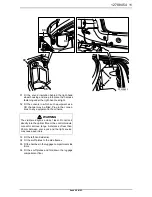
20 Fit the bumper-shell trim-moulding with the help

of the guide tabs and clip in the hooks, begin-
ning at the centre and working outwards.

21 Fit the seals to the sensors.
22 Fit together the distance sensors and the holders.
23 Fit the distance sensors to the mountings on the

trim moulding.

24 Connect the sensor wiring harness to the sen-

sors and fit it into the slots in the bumper shell.

25 Fit the support to the bumper shell.

Important

The connector sockets on the sensors should
point towards the right-hand side of the vehicle.

F930A050

21

22

23

25

24

24

24

Summary of Contents for 12 787 887

Page 1: ...ONTERINGSANVISNING INSTALLATION INSTRUCTIONS MONTAGEANLEITUNG INSTRUCTIONS DE MONTAGE SITdefault Saab 9 3 M03 Parking assistance SPA Accessories Part No Group Date Instruction Part No Replaces 12 787 887 9 40 03 Oct 02 12 788 454 12 788 454 Jul 02 F930A042 ...

Page 2: ...8454 Saab 9 3 M03 1 SPA control module 2 Holder x4 3 Seal x4 4 Distance sensor x4 5 Moulding bumper 6 Wiring harness distance sensor 7 SPA wiring harness 8 Dust cover 9 Cable tie x2 F930A054 1 9 5 7 6 2 3 4 8 ...

Page 3: ...and raise the vehicle 2 Remove the two nuts holding the air shield of the rear bumper against the body Remove the two screws holding the bumper shell against the wheel housings 3 Lower the vehicle and remove the rear bumper trim moulding 4 Open the hatchback F930A044 2 2 2 3 ...

Page 4: ... and remove the luggage compartment scuff plates 6 Remove the hatches from the luggage compart ment side trims 7 Remove the scuff plates from the side frames 8 Remove the clip for the left hand side trim and move the trim aside 9 Remove the rear lamp cluster F930A045 6 7 9 9 8 8 ...

Page 5: ...11 Remove the bumper bolts at the wheel housings 12 Remove the bumper shell by first pulling the side pieces outwards and then pulling the bump er shell rearwards 13 Remove the sound insulation from behind the right hand wheel housing Important Place the bumper on a clean soft surface F930A046 10 13 12 11 ...

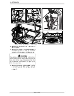
Page 6: ...Remove the rearmost connector blue from the rear electrical centre Make a note of how the rear wiring harness is connected and then remove it WARNING The visible red light is a class 1 laser Do not look directly into the optical fibre or the control module connector at close range A distance of less than 20 mm between your eyes and the light source may cause eye injury F930A047 16 16 16 16 16 16 1...

Page 7: ...e to the notes from the preceding point Fit a new dust cover and secure the harness components with a cable tie Important The harness attachment under the rear light should not be fitted yet as the sound insulation uses the same attachment F930A048 17 17 17 17 17 17 17 17 17 17 17 17 17 17 17 17 ...

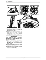
Page 8: ...8 12788454 Saab 9 3 M03 18 Plug in the control module and fit it onto the mounting point on the rear electrical centre 19 Remove the support from the bumper shell F930A049 19 18 ...

Page 9: ...rs 22 Fit together the distance sensors and the holders 23 Fit the distance sensors to the mountings on the trim moulding 24 Connect the sensor wiring harness to the sen sors and fit it into the slots in the bumper shell 25 Fit the support to the bumper shell Important The connector sockets on the sensors should point towards the right hand side of the vehicle F930A050 21 22 23 25 24 24 24 ...

Page 10: ...ell into place 28 Plug in the parking assistance harness connec tor and fit the connector into the hole beside the left hand rear light Fasten the wiring harness with a cable tie 29 Fit the bumper shell screws which are located below the rear lamp cluster 30 Fit and connect the rear lamp cluster Check the fit against the boot lid moulding WARNING Check that the wiring harness is not pinched Incorr...

Page 11: ...ment in the console 33 Fit the left hand side trim 34 Fit the scuff plates to the side frames 35 Fit the hatches in the luggage compartment side trims 36 Fit the scuff plates and fold down the luggage compartment floor WARNING The visible red light is a class 1 laser Do not look directly into the optical fibre or the control module connector at close range A distance of less than 20 mm between you...

Page 12: ...ode by putting the key in the ignition 46 Activate the window lifts pinch protection by running the side windows up and down twice A sound is made to verify activation 47 Connect the diagnostic tool select car and mod el year select All select Add Remove select the accessory and then Add Important This must be carried out with all remote controls otherwise they will not work Note The diagnostic to...

Reviews: