R5
SUPREME - Navigation System
INSTALLATION
7000 118-301, A3
Page 32
2.7
System interconnection without R5 NAV Junction box
System
Port
User
Port 1
User
Port 2
Speed
Log
Alarm
Output
RS-422 Ports
User
Port 3
User
Port 4
R4
Sensor
Alarm
ACK
Binary Ports
RS-422 Ports
R4 Nav Signal and Power Cable
R4 GPS Navigation Sensor or
R4 DGPS Navigation Sensor
(D)GPS Antenna
24 VDC/1A
External fuse
24 VDC/2A
External fuse
R5 Signal Cable DSUB-OPEN
R5 Power Cable
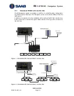
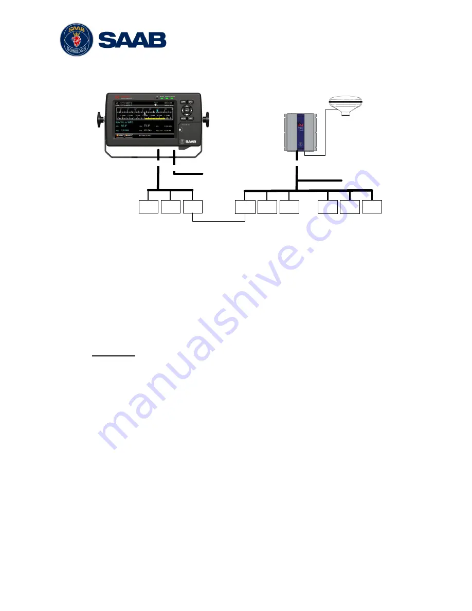
Figure 9
– Installation without R5 NAV Junction Box
2.7.1
R4 Sensor Power and Signal Cable
The R4 Sensor Power and Signal Cable, 7000 109-011 (ConXall to Open) is used
when there is no R5 NAV Junction Box available.
Figure 9 describes the system interconnection used in this case. The Navigation
sensor cable is connected by an 18-pin ConXall connector to the sensor and supplies
several different interfaces as indicated by Figure 9. The cable is also used to apply
power to the sensor.
Important:
The shield of the R4 Navigation Sensor power and signal cable (7000 109-011) is
ref
erenced to the negative DC supply.. For the same reason, don‘t connect the
Navigation Sensor alarm acknowledge signal ground, the speed log pulse signal
ground or the cable shield for the GPS antenna to the ship‘s structure.
Note: The Chassis of the R4 Navigation Sensor is not connected to any internal ground
and may thus be connected to the ship’s structure if desired.
2.7.2
R5 Signal Cable DSUB-Open
The R5 Signal Cable DSUB-Open is an open ended variant of the R5 Signal Cable
DSUB-DSUB. When this cable is connected to the R5 CDU I/O Port it will provide
signals as indicated in Figure 9.
Summary of Contents for R5 SUPREME AIS
Page 1: ...OPERATION INSTALLATION MANUAL Saab TransponderTech R5 SUPREME Navigation System ...
Page 2: ...This page is intentionally empty ...
Page 60: ...R5 SUPREME Navigation System OPERATION 7000 118 301 A3 Page 60 5 4 System Menus Tree View ...
Page 103: ...R5 SUPREME Navigation System OPERATION 7000 118 301 A Page 103 Figure 92 Update Software ...

