Chapter 3. Technical specifications of system Service Manual
– Dena 350
11
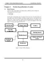
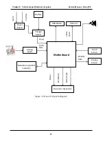
2.1.4 Power board
The power board performs AC/DC conversion in order to charge battery andsupply system
power. This board has medical label and its input and output are isolated above 4000Vac. This
board starts its functionality when connected to power line and continue its function as long as
remains connected to power line.
2.1.5 Battery Charger board
This board provides motherboard power with battery or power board. If power cable is
connected, the board charges battery (if necessary) with smart battery charger IC mounted on it.
In addition, this board is capable of transmitting data corresponding to battery remaining
capacity to motherboard.
2.1.6 Analog Board
This board is capable of acquiring, basic filtering and amplification of input signals from patient.
Also, this board converts analog signal to digital data with resolution of 16 bits.Another task of
this board is detection and removal of Pace signals before amplification. For this purpose, Pace
signals are attenuated as much as possible and then, a comparator circuit is used for pace
detection. Occurrence of pace is reported to motherboard through transmitted data. Also, board
can report disconnecting of lead or leads to the motherboard. For the safety of patient, an
isolation line (with isolation up to 4KVAC) is implemented.
2.1.7 Recorder Mechanism
Recorder mechanism has to print ECG signals on thermal paper. This mechanism consists of a
thermal head, a motor, and a paper holder frame. The motor has different speeds defined in the
systemand rotates bythe help of pulses sent by its driver and its power supply which is mounted
on the motherboard and as a result of motor force transmission with the help of gearboxes in the
mechanism, paper is fed out of mechanism. Furthermore, a thermal head is placed into the
mechanism which gets its commands from microcontroller and the data related to signals or texts
is loaded on it synchronous with each motor step.By activation/deactivation of dots on the head,
printing on the paper is performed.
2.1.8 Interface Board
Interface board handles communications with defined peripherals of the system. Defined ports of
the system are as below:
- SD Card Port which provides connection of SD Card to the board and stores data on SD Card.
Type: SD Card or Micro SD Card with Micro to SD adaptor, Size: 2 – 4 Gigabyte.
- USB Device Port which sends ECG raw data to the PC software.
- USB Host Port which is used for upgrading firmware.
- RJ-45 Port which is dedicated for connecting to local networks and is optional and for future
use.


