background image


Chapter 1.  Introduction                                                                          Service Manual 

– Dena 350


1.3.2


Bottom Panel 

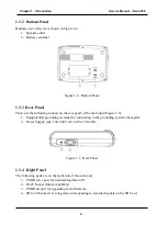
Bottom view of device is shown in Figure 1-4.  

1-


Speaker outlet 

2-


Battery container 


Figure 1-4   Bottom Panel


1.3.3


 Rear Panel 

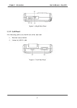
There are the following sockets on the rear panel of the main unit (Figure 1-5). 

1-


Equipotential grounding terminal for connecting to the grounding system of hospital. 

2-


Power Supply jack: 100-240 VAC, 60 VA 50/60 Hz. 


Figure 1-5   Rear Panel


1.3.4


Right Panel 

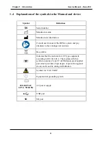
The following parts are on the right side of the main unit: 

1-


USB Device port for transmitting data to PC 

2-


RJ-45 Socket (future capability) 

3-


USB Host port for upgrading main firmware 

4-


SD Card Socket for saving data corresponding to recorded signals on the SD Card 


Summary of Contents for Dena 350

Page 1: ...SAADAT Co Service Manual Electrocardiograph D00720 V4 Dena 350...

Page 2: ...l 98 21 77960719 98 21 77962181 Fax 98 21 77964239 Customer Services Tel 98 21 73098000 98 21 77798910 Fax 98 21 77960761 Cell 98 912 1977157 Legal responsible Trionara Technologies AB Polygonv gen 21...

Page 3: ...0 Contents Chapter 1 Introduction 1 Chapter 2 Theory of operation 10 Chapter 3 Technical specification of system 12 Chapter 4 Installation 15 Chapter 5 Programming Instruction 16 Chapter 6 Test Calibr...

Page 4: ...ended to help detecting troubles and trouble shooting of the Electrocardiograph to the board level It is not permitted to service the printed circuit boards of system 1 2 Warnings Dena 350 Electrocard...

Page 5: ...paper and print ECG signals Recorder Release Button to open the recorder door Device Membrane to control the system operation LCD Screen ECG waveform patient information messages etc are contents dis...

Page 6: ...screen 12 lead ECG waveform Heart Rate value Patient ID Date and Time system operating status and error messages are displayed on the screen The screen is divided into four areas Header Area Waveform...

Page 7: ...on signal 6 Lead Press to select previous lead s 7 Lead Press to select next lead s 8 Start Stop Press to record ECG signals Press again to stop the recording 9 Reset Press to reset filters and bring...

Page 8: ...dicator lights up when the device is plugged in 17in Figure 1 3 Depending on remaining charge of battery battery indicator can be green orange or red when the battery is fully charged half charged or...

Page 9: ...unit Figure 1 5 1 Equipotential grounding terminal for connecting to the grounding system of hospital 2 Power Supply jack 100 240 VAC 60 VA 50 60 Hz Figure 1 5 Rear Panel 1 3 4 Right Panel The followi...

Page 10: ...duction Service Manual Dena 350 7 Figure 1 6 Right Side Panel 1 3 5 Left Panel The following parts are on the left side of the main unit 1 Recorder release button 2 Connector of ECG cable Figure 1 7 L...

Page 11: ...nd pay attention to the warnings and cautions Recyclable Indicates that the instrument is CF type equipment according to IEC 60 601 1 The module with this symbol contains a Type CF defibrillation proo...

Page 12: ...ing Menu Press Main menu and enter to Main menu window Select the Factory Settings Menu from System Settings Menu and enter it by the means of entering factory code FACTORY CODE abc Now you can Calibr...

Page 13: ...ntinuously checks inputs membrane and touch screen and in each page if correct input received responses appropriately In automatic records Microcontroller saves data on selected memory internal flash...

Page 14: ...d data Also board can report disconnecting of lead or leads to the motherboard For the safety of patient an isolation line with isolation up to 4KVAC is implemented 2 1 7 Recorder Mechanism Recorder m...

Page 15: ...parts are mounted with some screws in specified places In back panel power board and battery and battery charger board are assembled In front panel LCD recorder mechanism analog board andmotherboard...

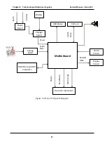
Page 16: ...gure 3 2 Dena 350 System Diagram Earth 220 Vac Serial Data Power Serial Data Parallel Data Power Serial Data Motor Pulse Power Board Battery Charger board Analog board Motherboard Membrane and LED Ind...

Page 17: ...m Service Manual Dena 350 14 3 2 Circuit diagrams part lists Last revision of circuit diagrams part lists are available on master document in POOYANDEGAN RAH SAADAT Co For more information please cont...

Page 18: ...ontinue working internal battery operation Make sure that the battery indicator lights on If it does not light check your local power supply and power cable connection If the problem still exists cont...

Page 19: ...rvice Manual Dena 350 16 Chapter 5 Programming Instruction For programming Dena 350 Analog board and motherboard ST Link programmer is used For more info please refer to ST Link programmer section in...

Page 20: ...r will be displayed on the main page in order to specify amount of charge left on the battery 4 Use all keys and go to different menus in order to make sure that functionality of all keys are OK 6 2 2...

Page 21: ...ties 5 If applicable the serial number of used equipment These records will be considered as a part of DHR Device History Record First the temperature and approximate humidity should be recorded and t...

Page 22: ...19...

Reviews: