Saberz Project
M Chassis Installation Guide
S
HTOK
NPXL
PCB
S
(V
ERSION
V3
SETUP
)
Version 1.9.5_b
–
September 18, 2022
•
Page 14
-
Solder the required wires (as seen in the wiring diagram at the bottom of this document) to the proper pads on
the bottom of the NPXL PCB.
-
Clean off the PCB with an appropriate PCB cleaner to remove residual flux before proceeding. We use WD-40
Specialist electrical contact cleaner spray and lightly brush around the soldered pads with a light bristle
toothbrush.
-
Gently attach the plastic lens to the PCB.
-
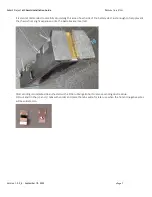
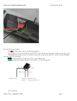
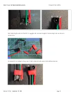
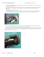
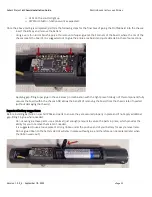
Form the NPXL
PCB wires into a “spring” (by tightly wrapping the wires around a paint brush handle) as seen
below. This will allow slack in the wires and ease of removal if you ever need to replace the NPXL PCB:
-
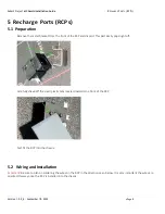
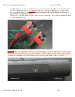
Carefully push the NPXL into place into the emitter. Later on (and after testing the completed chassis), use a
couple of really small dabs of gap-filling super glue to keep the lens in place.
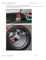
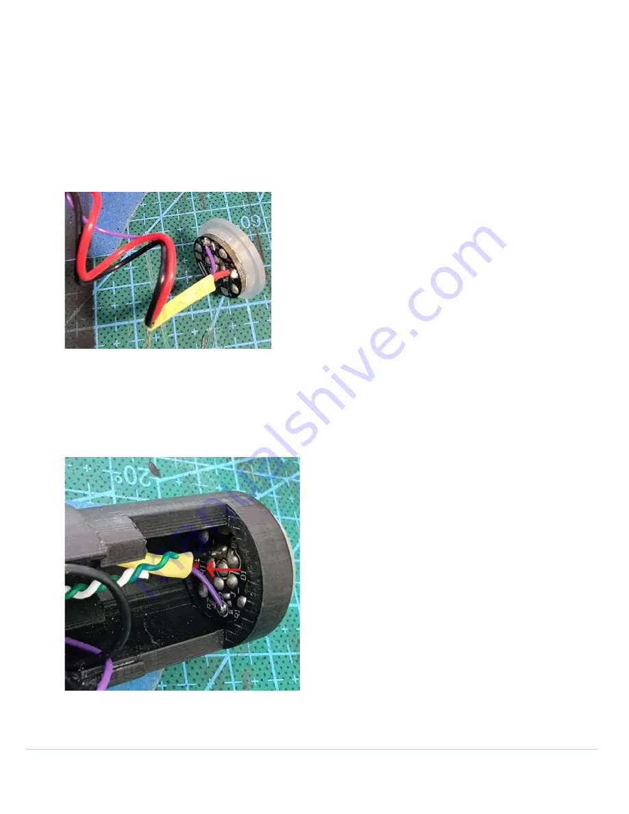
Important!
Be sure the NPXL PCB is oriented as seen in the below image, (with the NPXL PCB rotated so the wires are
located on the inner-most side of the chassis). This provides needed space for connecting the Micro USB connector
to the ProffieBoard later on in this area:

