
Saberz Project
M Chassis Installation Guide
P
ROFFIE
B
OARD
I
NSTALL AND
W
IRING
Version 1.9.5_b
–
September 18, 2022
•
Page 21
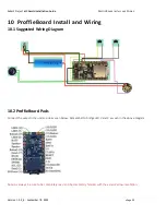
10.3
ProffieBoard Install
Once you have completed soldering all the connections to the ProffieBoard (for each of the two chassis in this set), you will
need to firmly press the 4 corners of the proffie to seat fully into place.
Steps:
-
Make sure you have NOT yet inserted the battery into the chassis!
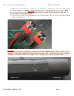
-
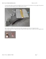
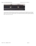
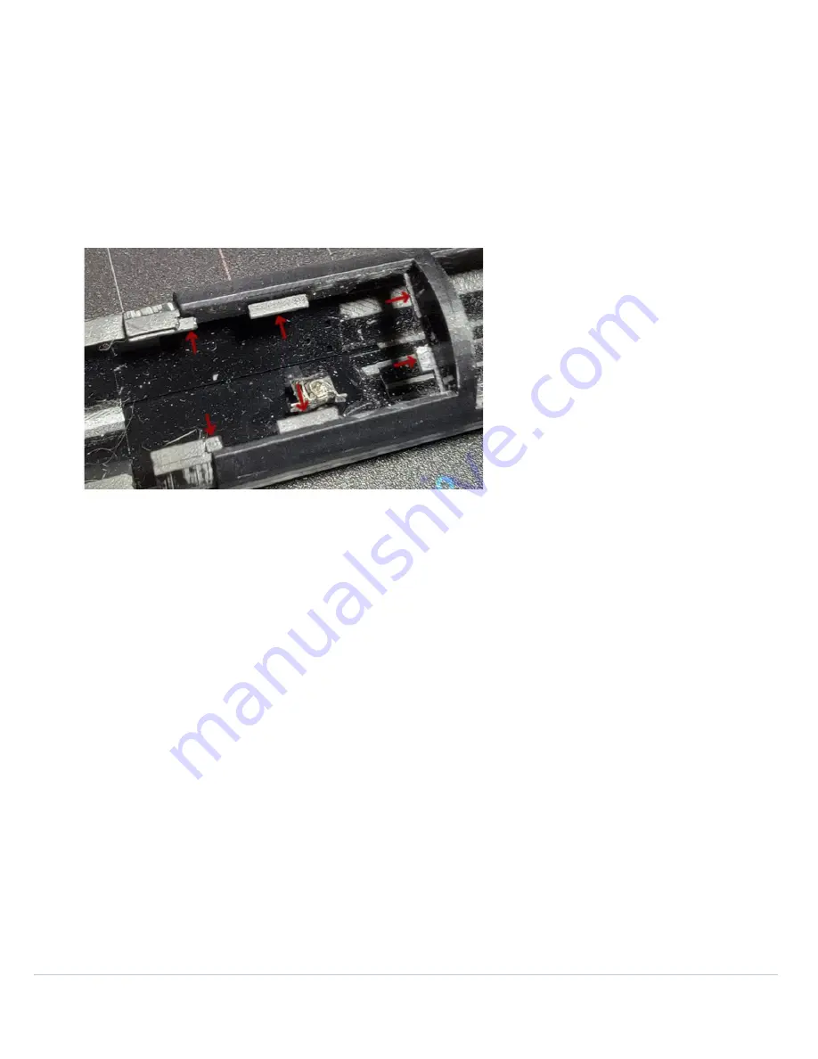
Be sure none of the wires are interfering with the support tabs (in which the ProffieBoard will reside on). Push these
wires under or otherwise out of the way of these tabs:
-
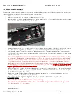
Firmly but carefully press the ProffieBoard into the proffie holder until you hear it snap into place, (you may have to
use a little pressure to get it to seat all the way, be careful not to damage the chassis during this process).
-
Visually inspect the board to ensure all corners have seated correctly. If it does not seat properly it could indicate
there could be a wire resting on one of the support tabs (or you did not sand the ribbed areas along the sides of the
ProffieBoard smooth.
-
Before proceeding further we always recommend cleaning the ProffieBoard one last time to ensure all traces of any
oils (from the handling process in the previous steps) are removed. This can be (very carefully) done by applying a
small amount of
“
WD-40 Specialist electrical contact cleaner
”
to a toothbrush and then gently brushing the top of
the ProffieBoard. Do NOT spray this product onto the ProffieBoard while it is installed in the chassis as it can be
damaging some 3D printed materials. Be SURE to wait a proper amount of time to allow all of the cleaner completely
dry BEFORE proceeding to the next steps. We recommend an hour just to be safe.
DO NOT use standard “WD
-
40”!!
Only use
“WD
-
40 Specialist electrical contact cleaner”
.
-
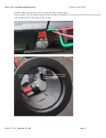
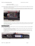
Now that the board is properly seated (and clean) it is safe to insert the SD card (containing your fonts) followed by
the battery. Note: Do NOT apply any glue just yet, it is best to test the board first and then come back later to glue
the ProffieBoard into place after testing.
-
Upload your configs to the ProffieBoard. (Follow the vendor user-guide for the correct programming method
including uploading your font folders to the SD cards).
-
After successfully uploading the configuration, test the functions by CAREFULLY turning on the chassis.
IMPORTANT NOTES:
-
Be SURE not to touch the ProffieBoard or any wires while testing!
-
NEVER attempt to test a NPXL blade with the chassis out of the hilt, doing so will cause the pins misalign and will
short out and destroy the ProffieBoard!!
-
Verify the following:


