background image

Saberz Project 

M Chassis Installation Guide 

P

ROFFIE

B

OARD 

I

NSTALL AND 

W

IRING


Version 1.9.5_b 

 September 18, 2022 


 Page 22 


o


LEDs on the emitter light up.


o


PWR/AUX button functions work as expected.


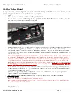
Once the above testing is completed, perform the following steps for the final task of gluing the ProffieBoard into the chassis:


-


Insert the kill key and remove the battery.


-


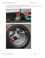
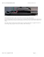
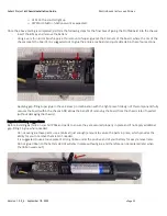
Using a very thin rod or brush, apply a thin amount of super glue (at the 4 corners of the board, where the rim of the 
chassis meets the board). It is suggested not to glue the entire area board and just add a dab in these four sections:


-


Applying gap-filling super glue in these 4 areas (in combination with the tight press-fit design of this component) fully 
secures the board within the chassis AND allows the benefit of removing the board from the chassis later if needed 
(without damaging the chassis). 

 
Important battery suggestions: 
Before installing batteries inspect all PCBs and parts to ensure they are secured properly in place and if not apply additional 
gap-filling CA glue where needed: 

-


Do not over-glue these parts, use a minimal (just enough) amount to secure the parts in place, which provides the 
ability for you to remove them later if needed.  

-


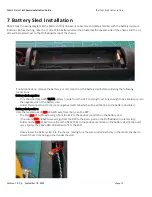
It is suggested to use a loose piece of strong ribbon under the positive end of your battery for easy removal later. 
Do not glue ribbon to the battery sled (it will stay in place without glue, and therefore can be replaced later when 
the ribbon wears out): 


Summary of Contents for Project M Chassis

Page 1: ...Project M Chassis Installation Guide Version 1 9 5_b September 18 2022 Page i Saberz Project M Chassis Installation Guide Version 1 9 5_b September 18 2022...

Page 2: ...harge Ports RCPs 8 5 1 Preparation 8 5 2 Wiring and Installation 8 6 Shtok NPXL PCBs Version V3 setup 13 6 1 Prepare the NPXL PCBs 13 7 Battery Sled Installation 15 8 Speakers 17 8 1 Preparations 17 8...

Page 3: ...ols Exact instructions for soldering the wires to your ProffieBoard are not provided only the wiring diagram we used for our installs Never use a heat gun anywhere near this chassis set as PLA SLS and...

Page 4: ...ts 7 8 NPXL blades Hero All features of the standard version Designed for 28mm Smuggler s Outpost speakers Requires modifications to the 28mm speakers as seen in the following YouTube video https www...

Page 5: ...impact fully painted and weathered kill keys in high impact Delrin for emitter side silver rivets Two aluminum RCP hex driven rivet RCP covers to protect the RCP port when kill keys are not in use Tw...

Page 6: ...ite 24mm 2w 4ohm Bass Speakers o For the 28mm version of the chassis 2 Smuggler s Outpost Elite 28mm Elite 2W 4OHM Bass Speaker Charger 1A 3 7V Li ion smart charger with 2 1mm plug 1 3mm recharge port...

Page 7: ...wer and switches GND Green Speaker White PWR tactile switch Speaker Yellow AUX tactile switch Violet DATA Soldering note set the soldering iron temperature to recommended settings per electronics vend...

Page 8: ...s area was intentionally designed for the proffie to tightly snap into place Be sure to sand any raised edges along the ProffieBoards and then ensure they press fit into place Test fit the speakers in...

Page 9: ...f each side of the battery sled Just enough to help prevent the chassis from slight expansion once the batteries are inserted After sanding is completed clean the sled with a little rubbing alcohol to...

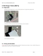
Page 10: ...of the RCP and discard This part easily pops right off Carefully shave off the small plastic tabs located towards the front of the RCP Test fit the RCP into the chassis 5 2 Wiring and Installation Im...

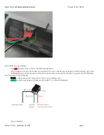
Page 11: ...nough wire so one can be later connected to the on the battery sled which will be directly next to the ProffieBoard area of the chassis and the other will be later connected to the BATT pad on the Pro...

Page 12: ...TS RCPS Version 1 9 5_b September 18 2022 Page 10 After soldering the wires to the RCP it is suggested to use small lengths of heat tubing to secure the wire connections Completed shrink tubing for th...

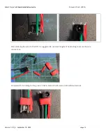
Page 13: ...to do this will likely result in the welds breaking from the movement of the wires during the install Also curling the green wire before installing the RCP will provide additional and much welcome eas...

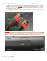
Page 14: ...n 1 9 5_b September 18 2022 Page 12 Install the RCP properly and secure it in place with gap filling superglue Once the glue is fully dry and cured carefully add a bead of hot glue to fully secure the...

Page 15: ...nd of the chassis The PCB should snap in and stop solidly at the thin raised inner ring which keeps the PCB at the correct placement Carefully push the PCB back out using wood dowel or eraser side of...

Page 16: ...ch the plastic lens to the PCB Form the NPXL PCB wires into a spring by tightly wrapping the wires around a paint brush handle as seen below This will allow slack in the wires and ease of removal if y...

Page 17: ...ry wire from the RCP to a length just long enough to be able to wire it to the negative side of the battery sled Solder this connection to the loose negative metal tab which will be slid back into the...

Page 18: ...ce the glue has dried use hobby tweezers to slide some of the green white twisted wire back into the speaker compartment just enough to provide enough wire slack for later on if you need to replace a...

Page 19: ...ite for positive Green for negative Use a razor to remove any tabs or imperfections which could interfere with a nice flat fit of the speaker against the chassis 8 2 Speaker Wiring and Installation So...

Page 20: ...t will be used for the PWR button The yellow and black set will be used for the AUX button Important Before proceeding note the tactile switches need to be installed directly against the inner portion...

Page 21: ...actile switches are very delicate To prevent these welds from being broken in later steps while moving the wires around inside the chassis it is recommended to apply a small drop of superglue or e6000...

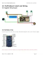
Page 22: ...Page 20 10 ProffieBoard Install and Wiring 10 1 Suggested Wiring Diagram 10 2 ProffieBoard Pads Connect the wires to the under side as seen below Remember to bridge LED 2 and 3 as seen in the above di...

Page 23: ...the handling process in the previous steps are removed This can be very carefully done by applying a small amount of WD 40 Specialist electrical contact cleaner to a toothbrush and then gently brushi...

Page 24: ...these 4 areas in combination with the tight press fit design of this component fully secures the board within the chassis AND allows the benefit of removing the board from the chassis later if needed...

Page 25: ...PCBs to be dry and free of PCB cleaner before installing your SD card and batteries Always use the kill key before inserting or removing batteries Always remove the batteries before performing any rep...

Page 26: ...ew a specific number of turns to set the screw plunger at the optimal distance above the tactile switches on the chassis Start out with the following general suggested distance settings and adjust as...

Page 27: ...the way down easily Insert the resin kill key rivet Slowly screw on the emitter housing do not force if it stops instead unscrew just a bit and then continue Screw down the PWR AUX buttons Repeat for...

Page 28: ...g such tasks 14 1 Example ProffieBoard Removal Process In the event of ProffieBoard hardware failure or the like the following steps outline how to remove the ProffieBoard from the chassis 1 Insert th...

Page 29: ...8 2022 Page 27 We hope you truly enjoy this chassis set as much as we do As always please feel completely free to contact us if you have any questions on the content of this document or anything regar...

Reviews: