background image

ISTRUZIONI PER L’INSTALLAZIONE DELLA SONDA ARIA

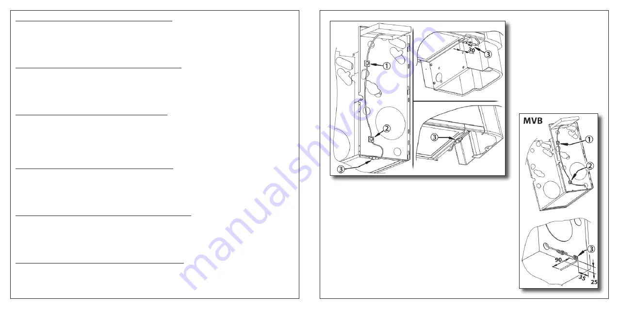
Posizionare N° 3 supporti adesivi sulla struttura interna come indicato nelle posizioni 1, 2 e 3. Successivamente tendere il cavo della

sonda fino alla posizione 1 e fissare con il primo supporto. Tendere leggermente il cavo e fissarlo al secondo supporto nella posizione 2.

Infine fissare la sonda nel terzo supporto rappresentato in posizione 3 dopo aver arrotolato e bloccato la parte eccedente di filo.

ATTENZIONE: 

Per un corretto funzionamento della sonda eseguire l’installazione come indicato nelle istruzioni.

INSTRUCTION FOR THE INSTALLATION OF THE AIR  PROBE

Place 3 adhesive supports on the internal structure according to position 1, 2 and 3. Then stretch the cable of the probe up to position 1

and fix it with the first support. Slightly stretch the cable and fix it in position 2 with the second support. At last fix the probe in the

third support shown in position 3 after having rolled up and locked the excessive part of the wire.

ATTENTION: 

For  a right working of the probe, you are requested to provide for installation according to the instruction.

ANLEITUNG FÜR DIE INSTALLATION DER LUFTSONDE

Die drei selbstklebenden Träger gemass den Angaben in den Positionen 1, 2 und 3 auf der internen Struktur positionieren. Dann

das Kabel der Sonde bis Position 1 spannen und mit dem ersten Träger befestigen. Das Kabel leicht spannen und es in Position 2 am

zweiten Träger befestigen. Schliesslich die Sonde am in Position 3 dargestellten dritten Träger befestigen, nachdem gem befestigen,

nachdem der überschüssige Anteil Draht aufgerollt und blockiert wurde.

VORSICHT: 

Für einen richtigen Betrieb des Fühlers, ist es nötig, daß die Installation weisungsgemäß durchgeführt wird.

INSTRUCTION POUR L’INSTALLATION DE LA SONDE AIR

Positionnez n°3 supports adhésifs sur la structure intérieure selon les indications des positions 1, 2 et 3. Après tendre le câble de la

sonde jusqu’à la position 1 et fixez-le avec le premier support. Tendre légèrement le câble et fixez-le au deuxième support en position 2.

Enfin fixez la sonde dans le troisième support représenté en position 3 après avoir roulé et bloqué la partie excédentaire du fil.

ATTENTION: 

Puor un correct fonctinnement de la sonde il faut exécuter l’installation comme indiqué dans les instructions.

INTRUCCIONES PARA LA INSTALACION DE LA SONDA DE AIRE

Posicionar 3 soportes adhesivos sobre la estructura interna como indica la posición 1, 2 y 3. Sucesivamente situar el cable de la sonda

hasta la posición 1 y fijar con el soporte. Tensar ligeramente el cable y fijarlo en el segundo soporte en la posición 2. Finalmente fijar

la sonda en el tercer soporte representado en posición 3 después de haber envuelto y bloqueado la parte eccedente de cable.

ATENCION: 

Para un correcto funcionamento de la sonda, es necesario efectuar l’instalacion confortemente a las instrucciones.

INSTRUCTIES VOOR DE INSTALLATIE VAN DE LUCHTSONDE

Plaats de drie zelfklevers in de binnenstructuur op de posities 1,2 en 3,zoals geillustreerd.Span vervolgens de kabel van de sonde tot

aan positie 1 en maak hen vast met de eerste zelfklever. Span de kabel lichtjes en maak hem met de tweede zelfklever vast op positie 2.

Bevestig tenslotte de sonde in de derde steun, weergegeven in positie 3, nadat u de resterende kabellengte hebt opgerold en vastgemaakt.

OPGELET: 

Voor een correcte werking van de sonde ,dient u de installatie uit te voeren volgens de instucties.

Summary of Contents for 9060134

Page 1: ...TION MANUAL STEUERUNG AUTOMATIKBETRIEB MIT ELEKTRONISCHEM THERMOSTATBEIDENUNGSLEITUNG COMMANDE AUTOMATIQUE AVEC THERMOSTAT ELECTRONIQUE MANUAL D ENTRETIEN MANDO AUTOMATICO CON TERMOSTATO ELECTRÓNICO MANUAL DE USO AUTOMATISCHE BEDIENING MET ELEKTRONISCHE THERMOSTAAT GEBRUIKSHANDLEIDING C 11 11 E 11 11 Cod 4050525 ...

Page 2: ...do sulla morsettiera IN1 un segnale elettrico di fase L 230V tramite un timer o un semplice interruttore è possibile ottenere la variazione della temperatura set impostata 3 C inverno 3 C estate DIP3 ON oppure l esclusione totale del funzionamento del ventilconvettore per i pe riodi nei quali i locali non sono abitati DIP3 OFF Durante il funzionamento estivo con ventilatore in OFF un timer metterà...

Page 3: ... setting selected by a Jumper J2 inside the control unit In four pipe fan coils with ON OFF water valves and the two liquids hot and cold water constantly present in the circuits automatic switching between heating and cooling phases according to the difference between set temperature and room temperature with a dead zone of 2 C By connecting a line signal L 230V on the terminal board IN1 a timer ...

Page 4: ...imultaneous thermostatic control on the valves and fan OFF OFF Thermostatic control on the valves for 4 pipes systems with automatic summer winter cycle switching according to the air temperature with 2 C dead zone DIP 3 Description of the functions ON Variation of night time set point 3 C winter 3 C summer OFF Disabling fan coil operation DIP 4 Description of the functions ON TME operation in the...

Page 5: ...den Anforderungen entspricht andernfalls die Kontrolleinheit entsprechend der gewünschten Funktionen programmieren EINGABEN DER FUNKTIONEN Art der Thermostatsteuerung ON OFF dip1 und dip 2 1 am Motor Klemme Nr 1 auf ON und Nr 2 auf ON 2 an den Ventilen Klemme Nr 1 auf OFF und Nr 2 auf ON 3 An den Ventilen und am Motor gleichzeitig Klemme Nr 1 auf ON und Nr 2 OFF Sommer Winterumschaltung JUMPER J2 ...

Page 6: ...de vannes eau ON OFF et avec la présence constante des deux fluides eau chaude et eau froide dans les circuits il est possible d obtenir la commutation automatique de la phase chauffage à celle de refroidissement et vice versa en fonction de l écart entre la température ambiante et la température programmée avec une zone morte de 2 C En branchant sur le bornier IN1 un signal électrique de ligne L ...

Page 7: ...ation simultanée des vannes et du ventilateur OFF OFF Thermostatation sur les vannes pour des installations à 4 tubes avec commutation automatique été hiver en fonction de la température de l air avec zone morte de 2 C DIP 3 Description de la fonction ON Modification de la température nuit 3 C hiver 3 C été OFF Exclusion du fonctionnement du ventilo convecteur DIP 4 Description de la fonction ON F...

Page 8: ...con una zona muerta de 2ºC Aplicando en la borna de conexión IN1 una señal eléctrica de línea L 230V mediante un temporizador o un simple interruptor es posible con seguir la variación de la temperatura establecida menos 3 C invierno más 3 C verano DIP3 ON o la exclusión total del funcionamiento del fan coil durante los periodos en que no se utilizan los cuartos DIP3 OFF Durante el funcionamiento ...

Page 9: ... voorzien van een ventilator convector met ON OFF waterkleppen en met een constante aanwezigheid van beide vloeistoffen warm en koud water in de leidingen kan de automatische omschakeling worden bekomen van de verwarmings en de afkoelingsfasen in functie van het verschil tussen de omgevingstemperatuur en de ingestelde temperatuur SET met een dode zone van 2 C Door een elektrisch lijnsignaal L 230V...

Page 10: ...OFF OFF Thermostaatinstelling kleppen voor installaties met 4 leidingen met automatische omschakeling zomer winter in functie van de luchttemperatuur en met dode zone van 2 C DIP 3 Beschrijving van de functie ON Variatie nachtinstelling 3 C winter 3 C zomer OFF Uitsluiting werking ventilator convector DIP 4 Beschrijving van de functie ON Werking TME in de zomercyclus OFF Werking TME in de wintercy...

Page 11: ...HT Für einen richtigen Betrieb des Fühlers ist es nötig daß die Installation weisungsgemäß durchgeführt wird INSTRUCTION POUR L INSTALLATION DE LA SONDE AIR Positionnez n 3 supports adhésifs sur la structure intérieure selon les indications des positions 1 2 et 3 Après tendre le câble de la sonde jusqu à la position 1 et fixez le avec le premier support Tendre légèrement le câble et fixez le au de...

Page 12: ...ning seizoensomschakeling Zomer Winter externe aansluiting uitgevoerd door de installateur CH Externe seizoensomschakeling LEGENDA MC Morsettiera del cablaggio MFC2 Morsettiera del FAN COIL SA Sonda aria TME Sonda di minima TME PE Messa a Terra Giallo Verde M Motoventilatore R Rosso velocità minima A Arancione velocità media N Nero velocità massima B Blu Comune E Valvola acqua Impianto a 2 tubi E1...

Page 13: ......

Reviews: