


13A
13
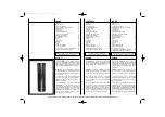
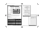
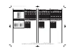
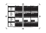
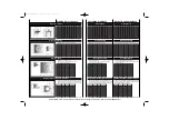
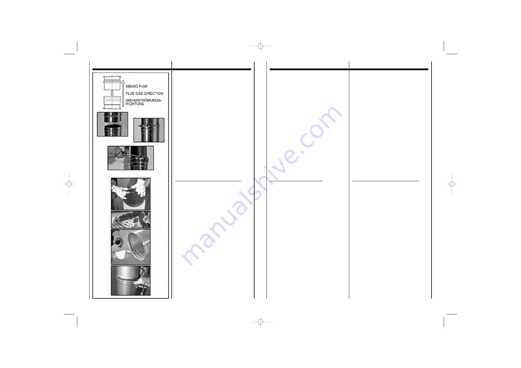
Sequenza operazioni:
1. Controllare con attenzione il progetto al fine
di identificare le caratteristiche tecniche di uti-
lizzo. Verificare, controllando l’etichetta sulla
confezione o la designazione sui moduli, che
il prodotto sia idoneo per l’utilizzo previsto dal
progetto.
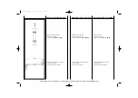
2. Ogni elemento ha una giunzione maschio ed
una femmina. Riferendosi al tubo l’estremità
maschio deve essere installata verso il basso.
Installare gli elementi secondo il senso dei fu-
mi seguendo la freccia indicata sugli elementi.
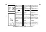
3. Durante l’assemblaggio assicurarsi che la giun-
zione maschio entri nel bicchiere femmina per
tutta la sua lunghezza.
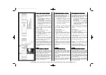
4. Installare la fascia di bloccaggio in modo che
racchiuda sia la bugna dell’innesto maschio
sia l’invito dell’innesto femmina.
5. Serrare la fascia di bloccaggio con un norma-
le avvitatore a stella.
I
STRUZIONI PER L
’
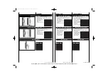
UTILIZZO DELLA GUARNIZIONE
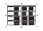
La guarnizione (di serie per il Ø 80 e Ø 100) deve
essere utilizzata obbligatoriamente in condizioni
di condensazione ed in presenza di pressione po-
sitiva (funzionamento ad umido W e la tenuta P1).
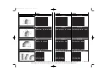
1. Prima dell’installazione di ogni modulo assicu-
rarsi che i giunti siano integri e puliti. Un modu-
lo diritto o un qualsiasi accessorio non può es-
sere utilizzato se piegato lungo il proprio as-
se. Eseguite tutte le verifiche, per i Ø maggiori
consigliamo di posizionare l’elemento in oriz-
zontale ed inserire la guarnizione nella sede,
appoggiandola verso il basso e accompagnan-
dola verso l’alto.
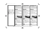
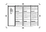
2. Se la guarnizione risultasse leggermente scar-
sa stirarla manualmente come rappresentato
in figura.
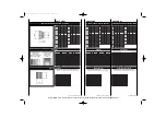
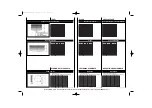
3. Lubrificare la guarnizione per facilitare l’in-
nesto.
4. Innestare l’elemento e montare la fascia di
giunzione serrandola con un normale caccia-
vite a stella. Durante l’installazione assicurarsi
che la fascetta di bloccaggio sia posizionata
in corrispondenza della gola del giunto.
5. Ripetere le operazioni sopra descritte ad ogni
giunzione.
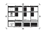
Operating sequence:
1. Carefully check the design so as to identify the
operating technical specifications. Check the
label on the packaging or the marking on the
modules so as to ensure the product is suitable
for the use required by the design
2. Each element has a male and a female joint.
In reference to the flue, the male end must be
installed downwards. Install the elements in
the direction of flue gas flow, as shown by the
arrow on the elements.
3. During assembly, check that the male joint is
fully inserted in the female socket.
4. Install the locking clamp so as to close the
indentation on both the male coupling and
the female coupling.
5. Tighten the locking clamp using a normal
star-head screwdriver.
I
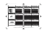
NSTRUCTIONS ON USING THE GASKET
The gasket (as standard for Ø80 and Ø100) must
be used in situations where condensate is formed
and when operating under positive pressure (wet
conditions W and tightness class P1).
1. Before installing each module, check that the
joints are intact and clean. Straight lengths or
accessories cannot be used if bent along their
axis. Once having carried out all the checks,
for the wider diameters the element should
be laid horizontally and the gasket inserted in
place, resting it on the bottom and pressing it
upwards.
2. If the gasket is too small, stretch it manually
as shown in the figure.
3. Lubricate the gasket to assist coupling.
4. Insert the element and fit the locking clamp,
tightening it with a normal star-head screw-
driver. During installation, check that the locking
clamp is located in the groove of the joint.
5. Repeat the operations described above for
each joint.
Vorgehensweise:
1. Definieren Sie anhand der Planung die tech-
nischen Nutzungseigenschaften. Überprüfen
Sie anhand des Etiketts auf der Packung oder
der Kennzeichnung an den Bauteilen, ob das
Produkt für die geplante Anwendung gebrauch-
stauglich ist.
2. Jedes eigene Bauteil hat eine Einsteckseite
und eine Muffenseite, wobei die Einsteckseite
des Rohrs nach unten zeigen muss. Installieren
Sie die Bauteile mit dem darauf abgebildeten
Pfeil in Abgasströmungsrichtung.
3. Schieben Sie bei der Verbindung das Spitzende
bis zum Anschlag in die Muffe.
4. Achten Sie bei der Installation des Klemm-
bands darauf, dass die Außensicken des
Spitzendes und der Muffe abgedeckt sind.
5. Spannen Sie das Klemmband mit einem
handelsüblichen Kreuzschraubenzieher.
A
NLEITUNG FÜR DEN GEBRAUCH DER DICHTUNG
Die Dichtung (serienmäßig für Ø80 und Ø100) muss
bei Kondensatbildung und Überdruck unbedingt
verwendet werden (Nassbetrieb W und Druck-
klasse P1).
1. Überprüfen Sie vor der Installation der Bauteile,
dass die Verbindungen unbeschädigt und
sauber sind. Längenelemente und sonstiges
Zubehör dürfen nicht verwendet werden, wenn
sie entlang ihrer Achse verformt sind.
Setzen Sie dann die Dichtung von unten nach
oben in die vorgesehene Sicke ein. Bei größeren
Durchmessern geht dies leichter, wenn die
Bauteile waagrecht liegen.
2. Falls die Dichtung etwas zu klein ist, muss
sie wie auf der Abbildung von Hand gezogen
werden.
3. Bestreichen Sie das Spitzende des Innenrohrs
mit Gleitmittel, um es besser einschieben zu
können.
4. Schieben Sie das Bauteil ein, montieren Sie
das Klemmband und spannen Sie es mit einem
handelsüblichen Kreuzschraubenzieher.
Das Klemmband muss bei der Installation auf
der Hohlkehle der Verbindung sitzen.
5. Führen Sie die Steckverbindungen der folgenden
Bauteile ebenso aus.
ISTRUZIONI DI MONTAGGIO
ASSEMBLY INSTRUCTIONS
MONTAGEANLEITUNG
Manuale INOX MONO 23-01-2008 11:03 Pagina 24
Cooke Industries - Phone: +64-9-579 2185 Fax: +64-9-579 2181 Email: sales@cookeindustries.co.nz Web: www.cookeindustries.co.nz


