14A
14
I
STRUZIONI DI MONTAGGIO MODULO TELESCOPICO
L’installazione e la manutenzione devono essere
eseguite da personale specializzato e qualificato.
I moduli telescopici, dato la loro funzione, non so-
no portanti per cui:
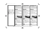
• In caso di installazione su tratti verticali uti-
lizzare immediatamente al di sopra un ac-
cessorio di supporto;
• In caso di installazione su tratti suborizzon-
tali prevedere l’utilizzo di accessori di staf-
faggio sia sul modulo precedente che quel-
lo successivo in modo da evitare flessioni
del canale da fumo.
In caso di installazione su un sistema condotto
e/o canale da fumo funzionante in pressione
(T200-P1) è necessario utilizzare la guarnizione
OR fornita a corredo.
Sequenza operazioni:
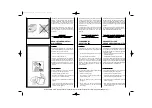
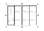
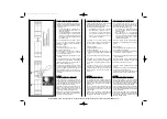
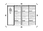
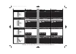
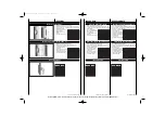
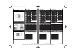
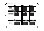
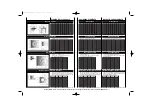
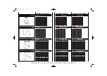
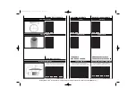
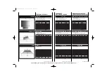
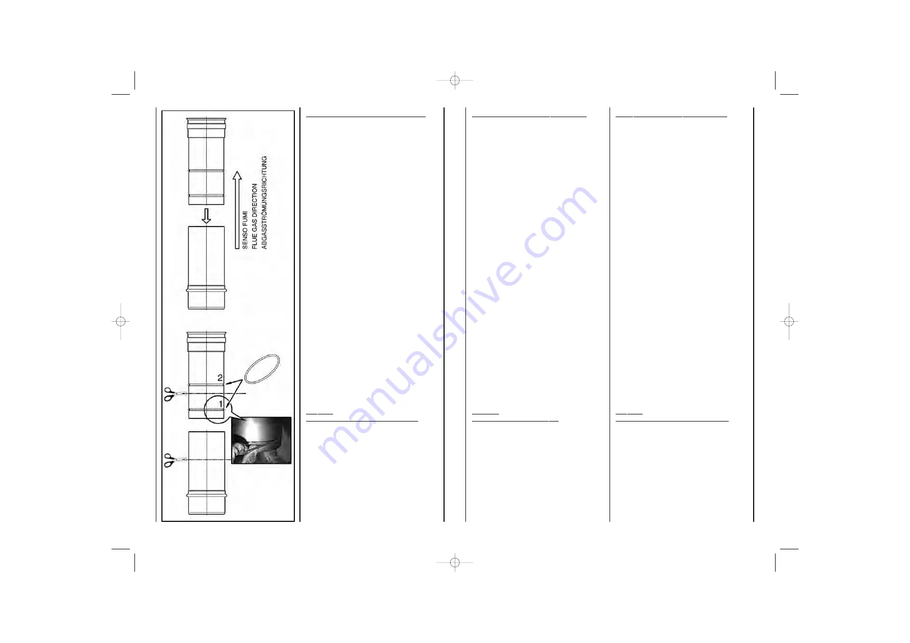
1. Installare la guarnizione nella sede 1.
2. Lubrificare la guarnizione.
3. Inserire il modulo che ha ad una estremità il
giunto femmina nel modulo che ha ad una
estremità il giunto maschio.
4. Regolare l’altezza del modulo alla misura de-
siderata.
In caso di installazione su un sistema condotto
e/o canale da fumo funzionante in depressione
(T600-N1) non utilizzare la guarnizione OR for-
nita a corredo (operazione 1 e 2).
Se necessario è possibile tagliare i tubi in modo
da ottenere riduzioni maggiori rispetto a quelle
originali. Per il taglio dei tubi utilizzare utensili che
non contaminano l’acciaio. In questo caso per un
sistema in pressione installare la guarnizione OR
nella sede 2.
I
NOX
M
ONO
A SERVIZIO DI GENERATORI A CONDENSAZIONE
Il prodotto InoxMono è certificato per il funziona-
mento ad umido. Per i condotti di diametro 80-100
le guarnizioni di tenuta sono previste di serie; per
i condotti di diametro 120÷300 le guarnizioni di
tenuta sono previste come accessorio.
Consigliamo di installare il canale da fumo in pen-
denza in modo da evitare il ristagno della con-
densa e di prevedere anche dei punti di scarico
condensa sui canali da fumo molto lunghi.
Sabiana SpA non risponde di perdite di condensa
dal proprio sistema camino causate dal mancato
o incorretto uso delle guarnizioni.
T
ELESCOPIC MODULE ASSEMBLY INSTRUCTIONS
Installation and maintenance must be performed
by specialist and qualified personnel.
The telescopic modules, given their function, are
not load bearing and consequently:
• For installation in vertical sections, use them
immediately above a support accessory;
• For installation in sub-horizontal sections,
use the bracket accessories on both the
previous and the subsequent module to
prevent the flue from flexing.
If installing on a flue and/or chimney system
operating under positive pressure (T200-P1),
the O-ring gasket supplied must be used.
Operating sequence:
1. Install the gasket in position 1.
2. Lubricate the gasket.
3. Insert the module with the female joint at one
end into the module with the male joint at one
end.
4. Adjust the height of the module as desired.
If installing on a flue and/or chimney system
operating under negative pressure (T600-N1) do
not use the O-ring gasket supplied (operation 1
and 2).
If necessary, the flues can be cut for further
reduction. To cut the flues, use tools that do not
contaminate steel. In this case, for systems under
positive pressure install the O-ring gasket in
position 2.
I
NOX
M
ONO
SERVING CONDENSING GENERATORS
The InoxMono product is certified for operation in
wet conditions. For the 80-100 diameter flues, the
gaskets are supplied as standard; for the 120-300
diameter flues, the gaskets are supplied as
accessories.
The flue pipe should be installed at an angle so
as to avoid the accumulation of condensate, while
condensate drain points should be used for very
long flue pipes.
Sabiana SpA is not liable for condensate leaks
from its system chimney due to the failure to use
the gaskets or the incorrect use of such.
M
ONTAGEANLEITUNG FÜR
T
ELESKOPBAUTEILE
Die Installation und Wartung müssen von
qualifiziertem Fachpersonal ausgeführt werden.
Teleskopbauteile sind aufgrund ihrer Funktion
keine tragenden Bauteile. Daher gilt:
• Bei Verwendung in vertikalen Abschnitten
müssen sie direkt oberhalb einer Konsole
installiert werden;
• Bei Verwendung in subhorizontalen
Abschnitten müssen am vorhergehenden
und am nachfolgenden Bauteil Halterungen
installiert werden, damit sich der Rauch-
gaskanal nicht durchbiegt.
Bei der Installation in einer Überdruckanlage
(T200-P1) muss der mitgelieferte O-Ring verwendet
werden.
Vorgehensweise:
1. Setzen Sie die Dichtung in die Sicke 1 ein.
2. Schmieren Sie die Dichtung.
3. Stecken Sie das Bauteil mit der Einsteckseite
in das Bauteil mit der Muffenseite.
4. Regeln Sie die Höhe des Bauteils auf das
gewünschte Maß.
Bei der Installation in einer Unterdruckanlage
(T600-N1) darf der mitgelieferte O-Ring nicht
verwendet werden (Vorgang 1 und 2).
Die Rohre können erforderlichenfalls gekürzt
werden.
Schneiden Sie die Rohre nur mit Werkzeugen,
die den Stahl nicht kontaminieren.
In diesem Fall muss der O-Ring bei einer Über-
druckanlage in der Sicke 2 installiert werden.
I
NOX
M
ONO
MIT RAUMLUFTUNABHÄNGIGER BETRIEBSWEISE
Das Produkt InoxMono ist für den Nassbetrieb
zertifiziert. Bei Rohren mit dem Durchmesser 80-
100 werden die Dichtung serienmäßig mitgeliefert;
bei den Rohren mit dem Durchmesser 120÷300
sind die Dichtungen als Zubehör erhältlich.
Um die Kondensatansammlung zu vermeiden,
sollte der Abgaskanal schräg geführt und sollten
an sehr langen Abgaskanälen Kondensatabflüsse
vorgesehen werden.
Sabiana SpA übernimmt keine Verantwortung,
wenn infolge von falschem oder unsachgemäßem
Gebrauch der Dichtungen Kondenswasser aus
dem Kaminsystem austritt.
Manuale INOX MONO 23-01-2008 11:03 Pagina 26
Cooke Industries - Phone: +64-9-579 2185 Fax: +64-9-579 2181 Email: sales@cookeindustries.co.nz Web: www.cookeindustries.co.nz


