background image

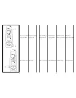
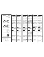
> 2 sec.

Fig. “G” / Obr. “G”

  •  Premere
    per più di 2 secondi
    il tasto “M” per tornare
    allo stato di funzionamento.

  •  Press the “M” button
    for more than 2 seconds
    to turn back
    to the operation mode.

  •  Appuyer pendant plus de 2
    secondes sur la touche “M”
    pour retourner
    à l’état de fonctionnement.

  • 

Stlač tlačítko “M”

    po dobu delší než 2 s
    pro návrat zpět
    do provozního režimu.

  •  Presione durante
    más de 2 segundos
    la tecla “M” para regresar
    al estado de funcionamiento.

  •  Druk langer
    dan 2 seconden op
    de toets “M” om terug te
    keren naar de bedrijfsstaat.

36

36a

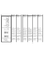
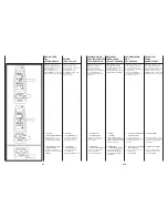
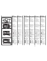
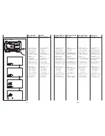
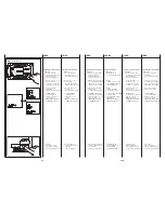
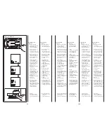
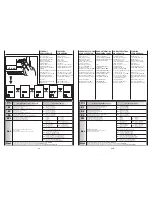
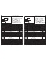
2) Programmazione
  (Fig. “G”):

  •  Premere il tasto “M”;
    il simbolo della modalità
    di funzionamento
    inizierà a lampeggiare.

  •  Premere il tasto (+) o (-)
    fino alla selezione
    del simbolo orologio “      ”;
    confermare con il tasto “M”.

  •  Premere il tasto “+”
    due volte; la scritta 

“Prd”

    apparirà sul display.
    Premere il pulsante “M”
    per confermare.

  •  Il display visualizza
    il messaggio 

On 1

, ora

    di accensione del primo
    giorno della settimana,
    e il messaggio 00:00.
    Tramite i tasti (+) o (-)
    impostare l’ora
    di accensione desiderata.
    Confermare
    con il tasto “M”.

  •  Il display visualizza
    il messaggio 

OF 1

, ora

    di spegnimento del primo
    giorno della settimana,
    e il messaggio 00:00.
    Tramite i tasti (+) o (-)
    impostare l’ora
    di spegnimento desiderata.
    Confermare 
    con il tasto “M”.

  •  Di seguito si passa
    alla programmazione
    di tutti i 7 giorni.
    Dopo l’ultima programma-
    zione premendo il tasto “M”
    si conferma e si torna
    alla visualizzazione
    del menù principale.

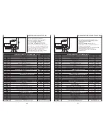
2) Programming
  (Fig. “G”):

  •  Press the “M” button;
    the operation mode
    symbol will start flashing.

  •  Press button (+) or (-),
    until selecting
    the watch symbol “      ”;
    confirm using the “M” button.

  •  Press button “+” twice;
    the abbreviation 

“Prd”

    will be displayed.
    Press the “M” button
    to confirm.

  •  The display shows
    the 

On 1

 message,

    start time of the first day
    of the week,
    and message 00:00.
    Using buttons (+) or (-),
    set the desired
    activation time;
    Confirm
    using the “M” button.

  •  The display shows
    the 

OF 1

 message,

    off time of the first day
    of the week,
    and message 00:00.
    Using buttons (+) or (-),
    set the desired
    deactivation time;
    Confirm
    using the “M” button.

  •  How to program all 7 days
    is explained below.
    After the last programming,
    press the “M” button
    to confirm and turn back
    to display the main menu.

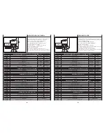
2) Programmation
  (Fig. “G”):

  •  Appuyer sur la touche “M”,
    le symbole du mode
    de fonctionnement
    commencera à clignoter;

  •  Appuyer sur les touches (+)
    ou (-) jusqu’à sélectionner le
    symbole de l’horloge “      ”;
    confirmer avec la touche “M”.

  •  Appuyer sur la touche “+”
    deux fois; le message 

“Prd”

    apparaitra sur l’écran.
    Appuyer sur le bouton “M”
    pour confirmer.

  •  L’écran affiche
    le message 

On 1

, l’heure

    d’allumage du premier jour
    de la semaine,
    et le message 00:00.
    A l’aide des touches
    (+) ou (-), configurer l’heure
    d’allumage souhaitée;
    Confirmer
    avec la touche “M”.

  •  L’écran affiche
    le message 

OF 1

, l’heure

    d’extinction du premier jour
    de la semaine,
    et le message 00:00.
    A l’aide des touches
    (+) ou (-), configurer l’heure
    d’extinction souhaitée;
    Confirmer
    avec la touche “M”.

  •  On passe ensuite
    à la programmation
    des 7 jours.
    Après la dernière
    programmation, on confirme
    en appuyant sur la touche “M”
    et on retourne à l’affichage
    du menu principal.

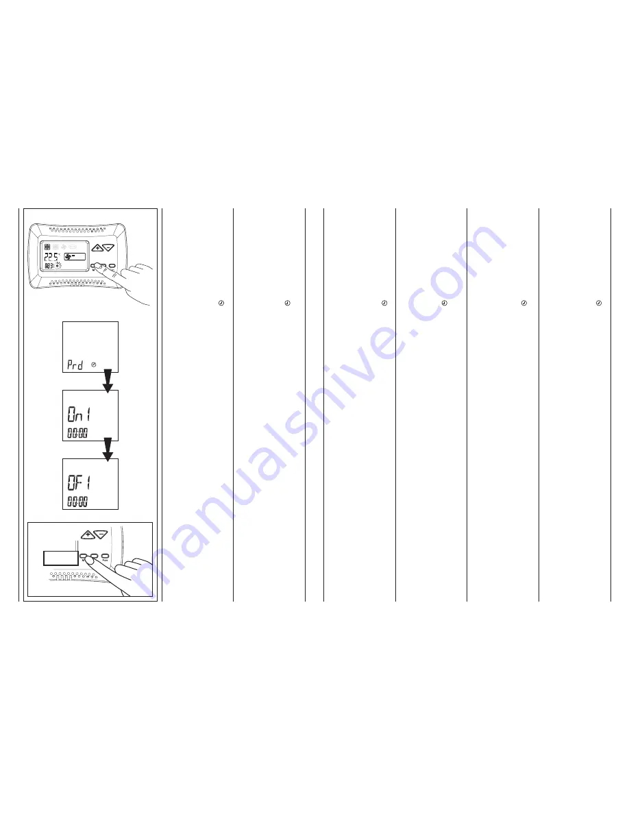
2) Programování
  (Obr. “G”):

  • 

Stlač tlačítko “M”

    a rozsvítí se symbol
    provozního režimu.

  • 

Stlač

    tlačítko (+) nebo (-) až se
    rozsvítí symbol “      ”;
    potvrď tlačítkem “M”.

  • 

Stlač

    dvakrát tlačítko “+”
    a rozsvítí se symbol 

“Prd”.

    Stlač tlačítko “M”
    pro potvrzení.

  • 

Display

    ukazuje informaci 

On 1

,

    čas spuštění
    první den v týdnu 00:00.
    Použitím
    tlačítek (+) nebo (-)
    je nastaven požadovaný
    čas spuštění;
    Potvrď tlačítkem “M”.

  • 

Display

    ukazuje informaci 

OF 1

,

    čas vypnutí
    první den v týdnu 00:00.
    Použitím
    tlačítek (+) nebo (-)
    je nastaven požadovaný
    čas vypnutí;
    Potvrď tlačítkem “M”.

  • 

Nastavení všech 7 dnů

    v týdnu je popsáno níže.
    Po ukončení posledního
    nastavení stlač tlačítko “M”
    pro potvrzení a návrat
    do hlavního menu.

2) Programación
  (Fig. “G”):

  •  Presione la tecla “M”;
    el símbolo de la modalidad
    de funcionamiento
    empieza a parpadear.

  •  Presione la tecla (+) o (-)
    hasta seleccionar
    el símbolo del reloj “      ”;
    confirme con la tecla “M”.

  •  Presione la tecla “+”
    dos veces; en la pantalla
    aparecerán las letras 

“Prd”

.

    Presione el pulsador “M”
    para confirmar.

  •  En la pantalla aparece
    el mensaje 

On 1

, la hora

    de encendido del primer
    día de la semana,
    y el mensaje 00:00.
    Con las teclas (+) o (-)
    programe la hora
    de encendido que desea.
    Confirme
    con la tecla “M”.

  •  En la pantalla aparece
    el mensaje 

OF 1

, la hora

    de apagado del primer
    día de la semana,
    y el mensaje 00:00.
    Con las teclas (+) o (-)
    programe la hora
    de apagado que desea.
    Confirme
    con la tecla “M”.

  •  A continuación
    se pasa a la programación
    de los 7 días.
    Tras la última programación,
    presione la tecla “M”
    para confirmar y regresar
    al menú principal.

2) Programmering
  (Fig. “G”):

  •  Druk op de toets “M”;
    het symbool
    van de modaliteit knippert;

  •  Druk op de toets (+) of (-),
    tot aan de selectie van het
    symbool van de klok “      ”;
    bevestig met de toets “M”.

  •  Druk twee keer op de
    toets “+”; het opschrift 

“Prd”

    verschijnt op de display.
    Druk op de knop “M”
    om te bevestigen.

  •  De display
    geeft 

On 1

 weer, het uur

    van de inschakeling
    op de eerste weekdag
    en het bericht 00:00.
    Met de toets (+) of (-) wordt
    het gewenste uur voor
    de inschakeling ingesteld;
    Bevestig
    met de toets “M”.

  •  De display
    geeft 

OF 1

 weer, het uur

    van de uitschakeling
    op de eerste weekdag
    en het bericht 00:00.
    Met de toets (+) of (-) wordt
    het gewenste uur voor
    de uitschakeling ingesteld;
    Bevestig
    met de toets “M”.

  •  Daarna kunnen de overige
    van de 7 weekdagen
    geprogrammeerd worden.
    Na de laatste programmering
    wordt op de toets “M”
    gedrukt om te bevestigen
    en terug te gaan naar de
    weergave van het hoofdmenu.

Summary of Contents for MB BOARD

Page 1: ...RD FOR CASSETTE FAN COILS USER MANUAL NOTICE D UTILISATION DE LA CARTE MB POUR VENTILO CONVECTEURS CASSETTE Deska MB pro kazetový FanCoil Návod na instalaci a údržbu MANUAL DE USO DE LA TARJETA MB PARA LOS VENTILADORES CONVECTORES CASSETTE HANDLEIDING MB KAART VENTILATORS CONVECTORS CASSETTE ...

Page 2: ...plafoniera sul cassette Batterie Note generali Impostazione orologio Impostazione del set desiderato Impostazione della ventilazione Modalità di funzionamento Timer Comando a parete T MB 2 3 4 5 5 6 6 7 8 8 10 11 12 13 15 19 19 20 21 23 24 25 26 27 29 SCOPO CONTENTS Scope Electronic board Function of the auxiliary contacts Setting the configuration dipswitches LED signal table Default configuratio...

Page 3: ...ve výrobě do přívodu vzduchu do fancoilu T2 CH15 25 termostat jako objednávkové příslušenství T3 Termostat minimální teploty Instalován z výroby Standardně deaktivován CF F2 F2 okenní kontakt přítomnost osob Je li rozepnut jednotka stojí CA F1 F1 vzdálené ON OFF ovládání nebo vzdálené přepnutí léto zima pomocí Change Over viz nastavení DIP9 RS485 Svorkovnice 0 D D pro sériové propojení přes RS485 ...

Page 4: ...ling DIP 9 met DIP 9 op OFF geconfigureerd als remote ON OFF waarbij rustcontact ON maakcontact OFF met DIP 9 op ON geconfigureerd als Zomer Winter waarbij 1 open Winter 1 dicht Zomer Contact CF F2 F2 contact open raam sonde aanwezigheid persoon ander systeem Bij gesloten contact werkt het apparaat Bij open contact stopt het apparaat Verwijder indien gebruikt de Jumper MC1 voor het afsluiten van h...

Page 5: ...ompa RL7 D0 D0 according to the pump RL7 D0 D0 couplé à la pompe IN1 Estate Inverno remoto IN1 Remote Summer Winter IN1 Été hiver à distance Slave 1 2 3 4 5 6 7 8 9 10 OFF OFF OFF OFF OFF OFF OFF OFF OFF OFF ON DIP DEFAULT OFF Posizione Position Position 2 TRUBKOVÉ ZAPOJENÍ INSTALACIÓN A 2 TUBOS INSTALLATIE MET 2 LEIDINGEN Termostatické ovládání ventilů Termostato con válvulas Thermostatering met ...

Page 6: ...té activa y que la regu lación se realice sobre las válvulas de agua Programando los Dip se puede intervenir con la regulación no sólo en las válvulas sino también en el ventilador pero habiendo progra mado una ventilación posterior de 3 minutos Cuando se llega al punto de ajuste la válvula de agua se desactiva y 3 minutos después el ventilador también se para Nota para evitar que fenómenos de est...

Page 7: ...e la commande T MB à un unique unité MAÎTRE Toutes les autres unités sont définies ESCLAVE Le fonctionnement de chaque appareil dépendra par contre des conditions relevées par celui ci selon la tem pérature mesurée Chaque fois qu on crée un réseau série il est important d en définir la fin en fermant le Jumper MC2 sur la dernière unité raccordées Note Le ventilo convecteur Maître devra Avoir le Di...

Page 8: ...force of less than 12 kg Higher forces may fray the wires and reduce the transmission properties do not twist knot crush or fray the wires do not lay the signal cables and power cables together if the signal cable needs to cross a power cable make sure the intersection is at 90 do not join sections of cable Always use one single cable to connect the units together les câbles doivent être tirés ave...

Page 9: ...a mínima de 2 metros de unidad con pesadas cargas inductivas cuadros de distribución motores generadores para sistemas de iluminación zet de geleiders niet overdreven aan in het klemmenbord Ontbloot zorgvuldig het uiteinde van de kabel Plet de kabel niet ter hoogte vanm de kabelhouder of de veiligheidshouders respecteer altijd de positie van de kleuren ter hoogte van de vertrek en aankomstpunten v...

Page 10: ...ého komunikačního kabelu Nikdy nepropojujte kabely křížem En la fase de conexión en serie de los aparatos respete la simbología de conexión borne D con borne D borne D con borne D borne 0 conectar el blindaje del cable de serie Nunca invierta las conexiones Bij de seriële aansluiting van de apparaten worden de aansluitsymbolen gerespecteerd klem D op klem D klem D op klem D klem 0 sluit de afscher...

Page 11: ...or Change Over Uitsluitend voor de ventilators convectors voorzien voor installaties met twee buizen kan de omschakeling zomer winter automatisch gebeuren door de sonde Change Over T2 optie te monteren op de waterleiding die de batterij voedt De sonde wordt vóór de driewegskleppen gemonteerd not to be used with 2 way valve In functie van de temperatuur gemeten door de sonde zal het apparaat zich a...

Page 12: ...vec résistance électrique M Ventilátor MB IR elektronická karta AT Autotransformátor C1 Kondenzátor EH Elektrické topné těleso E Topný a chladicí ventil 2 trubkové zapojení E1 Ventil topení 4 trubkové zapojení E2 Ventil chlazení 4 trubkové zapojení T1 Vzduchová sonda T2 CHANGE OVER T3 Termostat minimální teploty PŘIPOJENÍ GNYE Zeleno žlutý RD Červený minimální otáčky OG Oranžový střední otáčky BK ...

Page 13: ...3 BN 0 T2 T1 T2 J8 JP4B J9 WH 7 F1 F2 B2 BN JP4A D D 6 5 JP1 MC1 F1 JP2 0 WH J1 D D JP3 T3 F2 M1 B1 OG BN J5 WH RD BK OG M 1 C1 M9 BK WH BN BN JP5 J6 J4 BK BU BK BU WH J3 J7 AT OG BK RD BN BU L 4 D0 E2 2 N JP7 D0 E1 JP8 JP6 3 1 Impianto a 2 tubi 2 pipe units Installation à 2 tubes 2 trubkové zapojení Instalación a 2 tubos Installatie met 2 leidingen Impianto a 4 tubi 4 pipe units Installation à 4 ...

Page 14: ...TION 5 7 KD2 B3 BN 0 T2 T1 T2 J8 JP4B J9 WH 7 F1 F2 B2 BN JP4A D D 6 5 JP1 MC1 F1 JP2 0 WH WH RD J1 D D JP3 T3 F2 M1 10 JP9 0 M9 J3 BK BK WH RD GNYE 230Vac 50Hz E2 L N E1 PE BN BU BN BU 0 P A L 10VDC 0 10Vdc Input signal A P N P15V PE M 3 230V 50Hz L 4 D0 2 N JP7 D0 JP8 JP6 3 1 ECM BOARD POWER SUPPLY OG BN J5 WH B1 MB 14 14A SCHEMI DI COLLEGAMENTO Cassette con Motore Elettronico ECM CONNECTION DIA...

Page 15: ... la tuyauterie d eau et en modalité de chauffage active la vanne d eau si la température relevée est supérieure à 34 C ou bien la résistance si la température détectée est inférieure à 30 C Réglage DIP DIP 1 en ARRÊT DIP 6 en MARCHE DIP 7 en MARCHE et T2 branchée Pour le bon fonctionnement du capteur T2 il n est pas possible d utiliser la vanne à 2 voies qui empêcherait la circulation du fluide ch...

Page 16: ...ectric resistance coil as main heating element N B you can not mount the T3 probe on Cassette with electric heater fonctionnement avec résistance électrique comme élément de chauffage principal N B vous ne pouvez pas monter la sonde T3 sur Cassette avec la résistance électrique funkce s elektrickým ohřevem který je hlavním zdrojem tepla N B čidlo T3 není možné instalovat u kazetových FC s elektric...

Page 17: ...n Tset and Tenvironment N B you can not mount the T3 probe on Cassette with electric heater fonctionnement avec résistance électrique comme élément d intégration contrôle sur 2 plages Activation de la résistance en fonction du différentiel entre Tset et Tambiente N B vous ne pouvez pas monter la sonde T3 sur Cassette avec la résistance électrique funkce elektrického ohřevu jako integrovaného zdroj...

Page 18: ...ivation of the resistance coil depending on water temperature detection through T2 probe N B you can not mount the T3 probe on Cassette with electric heater fonctionnement avec la résistance électrique comme élément d intégration Activation de la résistance en fonction de la température de l eau détection de sonde T2 N B vous ne pouvez pas monter la sonde T3 sur Cassette avec la résistance électri...

Page 19: ...sette installation and maintenance manual Après avoir installé l appareil Cassette au plafond fixer le plafonnier en procédant comme suit 1 Poser le support du côté opposé au récepteur sur la Cassette 2 Fixer provisoirement le support à l aide du ressort 3 Raccorder la borne du récepteur à la borne du câble provenant de la carte 4 Poser tout le support sur la Cassette et le fixer provisoirement à ...

Page 20: ...ia insertar las baterías adjuntas Las baterías que se tienen que usar son del tipo AAA 1 5 Volt Alvorens de afstandsbediening te gebruiken worden de bijgeleverde batterijen geplaatst Gebruik batterijen van het type AAA van 1 5 Volt NON DISPERDERE LE BATTERIE NELL AMBIENTE UTILIZZARE GLI APPOSITI CONTENITORI SMALTITORI DISPOSE OF THE BATTERIES PROPERLY USING THE PROPER WASTE CONTAINERS NE PAS ABAND...

Page 21: ...Cassette Toto dálkové ovládání používá infračervené záření To znamená že pro korektní přenos signálu k IR přijímači na kazetovém fancoilu musí být dálkový ovladač nasměrován na IR přijímač a zároveň musí být dálkový ovladač v takové vzdálenosti aby IR přijímač byl v dosahu jeho vysílače viz obrázek Este mando a distancia es de rayos infrarrojos Esto significa que para transmitir las órdenes al apa...

Page 22: ...N SEND Cada vez que desee modificar los parámetros de funcionamiento del ventilador convector deberá enviar las instrucciones pulsando la tecla ON SEND Telkens wanneer men de werkingsparameters van de ventilator convector wenst te wijzigen worden de aanwijzingen doorgegeven met een druk op de toets ON SEND Per lo spegnimento dell apparecchio è invece sufficiente premere il tasto OFF To switch off ...

Page 23: ...er sur la touche de transmission ON SEND ou appuyer de nouveau sur la touche SELECT pour quitter le programme 2 Transmission mode de fonctionnement Pour envoyer l information à l appareil appuyer sur la touche ON SEND Nastavení hodin v dálkovém ovladači a nebo v kazetovém fancoilu 1 Změna nastavení Stiskněte tlačítko SELECT Na displeji začne blikat nápis CLOCK SET Stiskem tlačítka nebo údaj hodin ...

Page 24: ...te požadovaný údaj pro nastavení žádané teploty vzduchu v prostoru Pro odeslání nového nastavení stiskněte tlačítko ON SEND 1 Změna nastavení Pomocí tlačítek nebo nastavte požadovaný údaj pro nastavení požadované teploty vzduchu v prostoru 2 Odeslání dat do kazetového fancoilu Pro odeslání dat nového nastavení do kazetového fancoilu stiskněte tlačítko ON SEND Pulsando las teclas o aumente o dismin...

Page 25: ...se Grande vitesse Fonction automatique 2 Transmission mode de fonctionnement Pour envoyer l information à l appareil appuyer sur la touche ON SEND Stiskněte tlačítko FAN pro nastavení rychlosti ventilátoru K dispozici jsou čtyři režimy nízké střední a vysoké otáčky a režim automatické volby otáček Po nastavení požadovaného provozního režimu stupně otáček odešlete nové nastavení do zařízení pomocí ...

Page 26: ... appuyer sur la touche ON SEND Stiskněte tlačítko MODE pro nastavení zvoleného režimu provozu K dispozici jsou čtyři provozní režimy Pouze ventilátor Topení Chlazení Automatické přepínání mezi režimy topení chlazení podle aktuální požadované teploty v prostoru Tuto funkci lze použít u 4 trubkového zapojení je li trvale k dispozici jak topná tak chladicí voda 1 Změna nastavení Pouze ventilátor Tope...

Page 27: ...ncent à clignoter A l aide des touches ou programmer les minutes DŮLEŽITÉ Pokud není stisknuto žádné tlačítko po dobu cca 10 sekund opustí automaticky dálkový ovladač aktuální nastavovací menu a přejde do předchozího režimu beze změny nastavení 1 Změna nastavení Nastavení času zapnutí START Stiskněte dvakrát tlačítko SELECT Na displeji začne blikat nápis PROGRAM a START tiskem tlačítka nebo na dis...

Page 28: ... ON SEND Nastavení času vypnutí STOP Stiskněte tlačítko SELECT Na displeji začne blikat nápis PROGRAM a STOP Stiskem tlačítka nebo na displeji začne blikat údaj hodin Pomocí tlačítek nebo nastavte požadovaný údaj pro nastavení hodin Zmáčkněte tlačítko SELECT a na displeji začne blikat údaj minut Pomocí tlačítek nebo nastavte požadovaný údaj pro nastavení minut Stiskněte tlačítko SELECT Na displeji...

Page 29: ...stalaci může ovládat fan coily s instalovanou MB kartou a propojené v síti RS485 T MB zajišťuje následující funkce Obr 1 1 zapnutí a vypnutí zařízení 2 nastavení otáček ventilátoru 3 nastavení teploty 4 nastavení pracovního režimu Symboly na kontrolním panelu Obr 1 5 režim chlazení 6 režim topení 7 ventilátor 8 automatický režim 9 signalizace funkce elektrického ohřevu 10 signalizace funkce ventil...

Page 30: ...nen De gaten maken de pluggen in de muur plaatsen en het paneel met schroeven blokkeren De elektrische verbindingen uitvoeren zoals aangegeven wordt door het elektrische schema dat op de volgende pagina s gegeven wordt ATTENZIONE Per eseguire i collegamenti elettrici al comando T MB occorre rimuovere la protezione isolante dal morsetto Una volta eseguiti i collegamneti elettrici riposizionare la p...

Page 31: ...la correspondance de la numération commune à l ensemble des cartes Utiliser 3 conducteur avec une section de 0 5 mm2 NOTE La longueur du câble de raccordement ne doit pas être supérieure à 20 mètres Ovládací panel musí být připojen k základní desce umístěné uvnitř elektrického bloku fan coilu kazetového fan coilu ve shodě s odpovídajícím označením na svorkách Použij 3 vodiče s průřezem 0 5 mm2 Poz...

Page 32: ...RATURE AIR AMBIANT DIP N 2 SNÍMÁNÍ TEPLOTY VZDUCHU DIP č 2 HABILITACIÓN DE LA SONDA DE TEMPERATURA AIRE AMBIENTE DIP N 2 IN WERKING STELLEN SONDE TEMPERATUUR LUCHT OMGEVING DIP N 2 In particolare con il DIP N 2 è possibile definire quale sonda ambiente debba venir utilizzata Gli apparecchi cassette e Fancoil hanno infatti installata una sonda aria in ripresa sonda T1 Ugualmente anche il comando a ...

Page 33: ...rzení volby Selección de la modalidad Fig C Seleccione la modalidad de funcionamiento que desea presionando el pulsador M Seleccione la modalidad de funcionamiento que desea con las teclas o se configura la función de refrigeración se configura la función de calefacción se configura la modalidad automática de enfriamiento calefacción que puede utilizarse únicamente con instalaciones de 4 tubos se ...

Page 34: ...mer avec la touche M Appuyer sur la touche M pendant 3 secondes pour sortir du programme Stlačením na tlačítko M se zobrazí symbol režimu Stlač tlačítko nebo až se zobrazí symbol hodin Potvrď výběr tlačítkem M Stlač opět tlačítko pro dosažení režimu CLOCK a potvrď tlačítkem M Použij tlačítka nebo pro nastavení správného času Potvrď volbu tlačítkem M Stlas tlačítko nebo až se zobrazí den v týdnu da...

Page 35: ...tí symbol hodin potvrď tlačítkem M Stlač tlačítko M výběr pro zapnutí vypnutí Provozní stav hodin TIMER je v pozici OFF použij tlačítka nebo pro rozlišení TIMER OFF vypnuto TIMER ON zapnuto 1 Activación Desactivación Fig F Presione la tecla M el símbolo de la modalidad de funcionamiento empieza a parpadear Presione la tecla o hasta seleccionar el símbolo del reloj confirme con la tecla M Presione ...

Page 36: ...ches ou configurer l heure d allumage souhaitée Confirmer avec la touche M L écran affiche le message OF 1 l heure d extinction du premier jour de la semaine et le message 00 00 A l aide des touches ou configurer l heure d extinction souhaitée Confirmer avec la touche M On passe ensuite à la programmation des 7 jours Après la dernière programmation on confirme en appuyant sur la touche M et on ret...

Page 37: ... de la valeur de la sonde de minimale T3 Sonda non collegata diS Probe is not connected Sonde non branchée Nessun allarme No alarm Aucune alarme Visualizzazione stato del contatto finestra View status of the contact window Visualisation état du contact fenêtre Chiuso C Closed Fermée Aperto O Open Ouvert Visualizzazione di eventuali allarmi presenti View any alarms Visualisation des éventuelles ala...

Page 38: ...0 120 sec 40 sec F t3 Tempo di post ventilazione 5 240 sec 60 sec FUNZIONE DESCRIZIONE RANGE DEFAULT PARAMETRI TERMOSTATO Solo per versione T MB ECM Slu1 SCu2 Tensione min velocità Tensione med velocità 1 6 1 V 3 8 5 V SHu3 Tensione max velocità 6 10 10 V LLSI Tensione min velocità per fan auto inverno 1 6 1 V HLSI Tensione max velocità per fan auto inverno 5 10 10 V LLSE Tensione min velocità per...

Page 39: ...r uniquement pour Cassette Temps ventilateur ARRÊT Temps RL2 MARCHE Temps post ventilation Tension min vitesse Tension moyenne vitesse Tension max vitesse Tension min vitesse pour ventilateur automatique hiver Tension max vitesse pour ventilateur automatique hiver Tension min vitesse pour ventilateur automatique été Tension max vitesse pour ventilateur automatique été Bande proportionnelle de refr...

Page 40: ...nvierno sólo para Cajas Fan OFF tiempo RL2 ON tiempo Tiempo de post ventilación Velocidad min tensión Velocidad media tensión Velocidad máx tensión Velocidad min tensión para el ventilador de invierno automático Velocidad máx tensión para el ventilador de invierno automático Velocidad min tensión para el ventilador de verano automático Velocidad máx tensión para el ventilador de verano automático ...

Page 41: ......

Reviews: