46
English
»
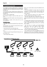
Master&Slave operation
It is possible to connect several devices to each other
and control them simultaneously by transmitting the
settings from the control (optional accessory) to a single
MASTER unit.
The operation of each individual device will depend on
the conditions detected by the control connected to the
MASTER unit.
All other units are called SLAVE.
Max. distance between control and first power unit:
20 m.
The total length of the network must not be longer than
100 metres.
The maximum number of fan coils that can be
connected is 16.
Installation notes
- the cables must be tensioned with a force of less than
12 kg.
Increased force can weaken the leads and thus reduce
the transmission properties;
- do not twist, knot, crush or fray the leads;
- do not lay the signal lead together with the power
ones;
- if you have to cross the signal lead with the power one,
cross them at 90°;
- do not splice cable sections.
Always use a single cable to connect the individual units
together;
- do not overtighten the leads under the terminal
connections. Strip the end of the cable carefully and
carefully. Do not crush the cable at the cable splices or
safety supports;
- always respect the position of the colours at the
starting and finishing points of the connection;
- once the wiring has been completed, visually and
physically check that the cables are intact and correctly
laid;
- install the cables and units in such a way as to minimise
the possibility of accidental contact with other power
cables or potentially dangerous cables such as lighting
system cables;
- do not lay 12 V power and communication
cables near power bars, lighting lamps, aerials,
transformers, or hot water or steam pipes;
- Type of lead to be used: 3 x 0.5 mm² (for Master&Slave
connection with wall control WM-AU)
- Type of lead to be used: Data cable RS485 characteristic
impedance 120 ohm type 1x2xAWG24 (1x2x0.22 mm²)
(for Master&Slave connection with wall control WM-AU).
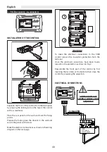
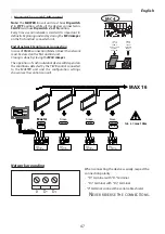
MAX 16
tot. L = max 100m
L = max 20m
Slave
Slave
Slave
Master
5
6
7
MC4
MC2
M3
M2
M1
D+
0
7
6
5
6
0
D-
10V
0
5
DI1
EVO
POWER UNIT
MC4
MC2
M3
M2
M1
D+
0
7
6
5
6
0
D-
10V
0
5
DI1
EVO
MC4
MC2
M3
M2
M1
D+
0
7
6
5
6
0
D-
10V
0
5
DI1
EVO
MC4
MC2
M3
M2
M1
D+
0
7
6
5
6
0
D-
10V
0
5
DI1
EVO
ELETTRONIC
POWER BOARD
CFF
ELETTRONIC
POWER BOARD
CFF
ELETTRONIC
POWER BOARD
ELETTRONIC
POWER BOARD
°
C
IAQ
AUTO
AUTO
CFF
CFF
»
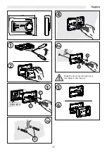
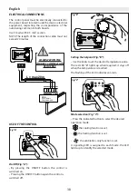
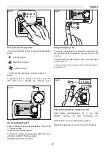
Master&Slave with WM-AU control
Summary of Contents for UP-TOUCH
Page 4: ...4 Italiano Montaggio del comando CB E A B A B CTRL CTRL C...
Page 8: ...8 Italiano Montaggio del comando CB Touch A B CTRL C CTRL B CTRL C CTRL A B...
Page 27: ...27 English Installation of the CB E control A B A B CTRL CTRL C...
Page 31: ...31 English Installation of the CB Touch control A B CTRL C CTRL B CTRL C CTRL A B...
Page 50: ...50 Fran ais Montage de la commande CB E A B A B CTRL CTRL C...
Page 54: ...54 Fran ais Montage de la commande CB Touch A B CTRL C CTRL B CTRL C CTRL A B...
Page 73: ...73 Deutsch Montage der CB E Steuerung A B A B CTRL CTRL C...
Page 77: ...77 Deutsch Montage der CB Touch Steuerung A B CTRL C CTRL B CTRL C CTRL A B...
Page 96: ...96 Espa ol Montaje del mando CB E A B A B CTRL CTRL C...
Page 100: ...100 Espa ol Montaje del mando CB Touch A B CTRL C CTRL B CTRL C CTRL A B...


