Internal Calibrations
Page 8-14
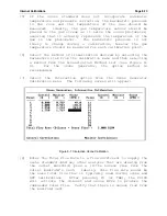
[9] In order to obtain the best accuracy, he calibration table
should contain points below the lowest point needed during
ozone
or
GPT
calibrations
and
above
the highest.
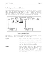
Experimentally determine what control voltages are needed to
produce these low and high ozone concentrations by entering
a voltage in the left-most column and observing the
resulting concentration as measured by the ozone standard.
Pressing F2 (or Shift-TAB) will back up to allow another
voltage to be entered.
Once the calibration voltage range has been bracketed,
determine a set of control voltages needed to produce
roughly equally spaced calibration points for the number of
points desired. Before calibration, the ozone generator is
slightly non-linear at the low end, so the voltage setpoints
should be more closely spaced there.
[10] Enter the first control voltage in the left-most column.
The
2010D
will apply this voltage to the UV Power
Supply which drives the ozone lamp, causing ozone to be
produced.
[11] Observe that the monitor voltage approaches the control
voltage, indicating that either the current or optical
sensor is sensing that the lamp is active. Also observe the
response of the ozone standard. It normally takes several
minutes before the ozone standard reaches its final value.
[12] Once the ozone standard’s reading has stopped changing and
reached a final value, take several measurements at
intervals of 20 to 30 seconds and average them together. If
the ozone standard requires temperature and pressure
correction, take a temperature reading and apply it and the
room’s barometric pressure to the measured ozone in order to
obtain a corrected value. Enter this value into the column
labeled "Ozone" and press the Enter key. The cursor will
advance to the next control voltage field.
[13] Repeat steps 10 through 12 until all calibration points have
been entered.
Summary of Contents for 2010D
Page 1: ...MODEL 2010D GAS DILUTION CALIBRATOR OPERATIONS MANUAL I N S T R U M E N T S...
Page 3: ......
Page 20: ...System Operations Page 3 2 Figure 3 1 The Model 2010D Front Panel...
Page 42: ...Installation Page 4 15 Figure 4 1 Rear Panel...
Page 63: ...Operation Page 5 7 Figure 5 5 The Dilution Status Screen Figure 5 6 The Ozone Status Screen...
Page 177: ...MODEL 2010D GAS DILUTION CALIBRATOR SCHEMATICS...
Page 178: ......


