Operation
Page 5-1
Section 5 Operation
This section introduces the customer to the use and day-to-day
operation of the Model
2010D
. The operations described here
assume that the
2010D
has already been configured for a specific
application as described in Section 6.
Performing Automatic Calibrations
Upon power-up, the Model
2010D
is placed in a "Standby" mode,
waiting for time to perform automatic scheduled calibrations or
to initiate calibration sequences or points in response to
remote control commands. The
2010D
is always ready to initiate
automatic scheduled calibrations unless manual calibrations are
being
performed.
When
performing
manual
calibrations,
automatically scheduled calibrations will not take place, but
will be postponed until the next scheduled time.
Calibration Sequences and Diluent and Source Gases must be
defined before performing automatic calibrations. Refer to
Section
6,
"Model
2010D
Calibration
Set-up",
for
more
information.
Automatic calibrations can either be activated externally by a
device such as a data acquisition system or internally by the
The Model
2010D
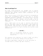
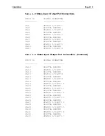
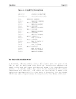
has 24 digital I/O bits that
Model
2010D
's
clock. can be
activated
externally to initiate auto calibration
sequences.
Depending upon how the I/O bits are assigned, the
external device can either step the
2010D
through each
calibration point contained in the calibration sequence or
initiate a calibration sequence, allowing the
2010D
's timer to
step through each calibration point.
Automatically timed sequences are set up as described in the
subsection "Scheduling Automatic Calibrations" in Section 6.
Externally activated sequences and sequence points are assigned
to digital I/O bits as described in the topics "Assigning
Sequence Start Patterns" and "Assigning Point Start Patterns",
in Section 6. Wiring is covered in the subsection titled
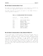
"Status Input/Output Port" Section 4.
Summary of Contents for 2010D
Page 1: ...MODEL 2010D GAS DILUTION CALIBRATOR OPERATIONS MANUAL I N S T R U M E N T S...
Page 3: ......
Page 20: ...System Operations Page 3 2 Figure 3 1 The Model 2010D Front Panel...
Page 42: ...Installation Page 4 15 Figure 4 1 Rear Panel...
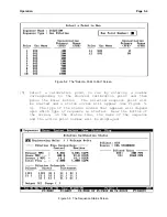
Page 63: ...Operation Page 5 7 Figure 5 5 The Dilution Status Screen Figure 5 6 The Ozone Status Screen...
Page 177: ...MODEL 2010D GAS DILUTION CALIBRATOR SCHEMATICS...
Page 178: ......


