9
GB
Adjusting the cutting height (Illustration I )
Safety instruction!
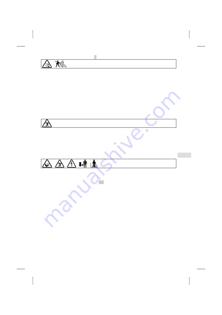
See table for explanation of symbols page 3
The mower is adjusted to the lowest cutting height upon delivery.
– The cutting height is set on the left hand side of the lawnmower
– Press the red button with your thumb and move the handle of the lawnmower into the required position by moving it up
or down.
– By letting go of the button, the lever locks into the required cutting height.
– The marking on the left on the adjusting rod indicates the cutting height.
IMPORTANT
Mowing at the lowest cutting height should only be carried out on level and plane lawns!
Please observe that the lower cutting height settings may only be used for optimal conditions. If you select cutting
height that is too low, the turf can be damaged and under certain circumstances it can even be destroyed.
Besides the cutting height, also the moving speed influences the cutting pattern and collection result. Adapt the
cutting height and moving speed to the grass height to be cut.
8
BEFORE USING THE LAWNMOWER FOR THE FIRST TIME
Safety instruction!
See table for explanation of symbols page 3
Check all screw connections for a tight fit. Tighten the screws if necessary. Attachment of the cutter bar must be checked in
particular (refer here to the chapter "Cutter bar care").
The blade attachment screw must always be tightened by an authorised workshop since an insulation protection test always
has to be carried out after repairs or maintenance work on insulation parts (e.g. blade screw) in accordance with the
applicable standard DIN EN 60335.
Make sure that all protective devices have been attached properly and are not damaged.
9
STARTING THE MACHINE
Safety instruction!
See table for explanation of symbols page 3
IMPORTANT
If the unit is to be operated via a generator, an authorised specialist workshop should first be consulted with regard
to a suitable generator.
Attaching the connecting cable (Illustration C2 )
NOTE
In order to guarantee the proper and safe operation of the garden equipment, a connection cable of the minimum
quality H05 RN-F (alternatively H05 VV-F) in accordance with DIN/VDE 0282/4 with a cross-section of 3 x 1 mm² and a
connection plug made of or covered with rubber in accordance with DIN/VDE 0620 are required. Connection must be
to a CEE 7/4 socket 230 V AC, slow-blow 16 A fuse.
When a childproof cable is used, care must be taken that the fuse works perfectly (smoothly) as otherwise the
device connection plug could become damaged.
IMPORTANT
Cables with a cross-section of 3 x 1 mm
2
should only be used up to a length of 25 metres. If a connection cable with
a cross-section of 3 x 1.5 mm
2
is used, the length of the connection cable can be up to 40 metres.
– Plug the cable into the switch/plug combination on the upper handle.
– Only then should the connecting cable be connected to the mains.
– When removing the cable always disconnect the cable plug from the mains first.
Summary of Contents for 36-EL
Page 5: ......
Page 6: ...A1 E1 B1 Q1 R1 S1...
Page 7: ...I C2 D2 A2 F M...
Page 12: ...U2 J K L O N...
Page 13: ...Q S...
Page 14: ......
Page 82: ...2 RU 1 1 2 3 4 5 6 7 8 GS 9 10 11 12 CE 13 14 2 SABO SABO SABO Maschinenfabrik GmbH...
Page 83: ...3 RU 3 DIN EN 60335...
Page 84: ...4 RU 4 SABO 5 16...
Page 85: ...5 RU H05 RN F H05 VV F DIN VDE 0282 4 3 x 1 DIN VDE 0620 230 16 30...
Page 86: ...6 RU 30 15 C 1...
Page 87: ...7 RU 3 3 11 4 6 2 12 H 05 RN F H05 VV F DIN VDE 0282 4 DIN EN 60335...
Page 88: ...8 RU DIN EN 60335 DIN EN 60335 30 6 1 2 3 4 5 6 7 8 9 10 11 12...
Page 89: ...9 RU 7 A1 E1 B1 Z A1 E1 B1 B1 E1 B1 Q1 R1 S1 Q1 Q1 R1 R1 1 S1 I 3...
Page 91: ...11 RU 5 1 2 3 4 5 6 10 F 3 11 3 12 3 1 S1 J K J K L...
Page 92: ...12 RU 13 3 30 15 3 DIN EN 60335 10 32 32 BImSch V M 10 14...
Page 93: ...13 RU DIN EN 60335 10 1 3 1 3 1 2...
Page 94: ...14 RU U2 S1 U2 S1 14 10 50 1 15 3 O...
Page 95: ...15 RU A1 Z A1 N N Q DIN EN 60335 1 Q 30...
Page 96: ...16 RU DIN EN 60335 S 50 16 5 C2 I Q I...
Page 97: ...17 RU J K L I 1 3 10 I U2 S1 I I...
Page 98: ......


