Operating manual - ChillPAC and LP ChillPAC Mk 3
36/68
010823 en 2021.06
4. Installation information
4.1
General information
For assistance or information about installation, please contact your local Johnson Controls
product representative.
4.2
First start-up procedure
Installation in terms of mechanical work (refrigeration system and piping), electrical work and installation
of safety equipment must be performed in accordance with local codes/rules and/or according to EN
378-3 and EN 378-4 as minimum requirements.
The pressure loss in the downstream line from the safety valve must meet the values stated in EN
13136 to which EN 378 is referring. The data necessary to dimension the line in accordance with this
standard is stated in the data sheet for the specific unit in the beginning of this manual.
Make sure that all necessary documents are available including declarations, certificates, identification
plates, manuals, machine card, logbooks, etc. and/or other documentation required according to local
rules and/or EN 378.
The main issues/check points for installation of the compressor unit are as follows:
1.
Lifting the unit. Only use the lifting lugs marked with red.
2.
Place the unit with sufficient free space for operation and maintenance in accordance with GA-
drawing.
3.
Place the unit on a foundation suitable for the actual load and vibrations. With or without vibra-
tion dampers according to the vibration design strategy.
4.
Connect all piping. The piping design must include considerations regarding function, suspen-
sion, vibrations, thermal expansion and pre-stress after welding in order to avoid high load on
the chiller unit connections. Mount all hoses and valves for compressor cooling.
5.
The safety valves are fitted on the unit from factory. The pipe connection to the valve discharge
branch must be made in accordance with existing rules/standards. External piping and condens-
ers are not protected by the safety valves fitted on the unit.
6.
Leak and pressure testing according to the applied/local codes and rules. Isolate the compres-
sor unit from the test pressure or disconnect the pressure transducers and safety valves. Never
exceed the test pressure of the unit stated on the unit name plate. All chiller units are pressure
tested and performance tested from factory.
7.
Connect power supply wiring (water/brine pumps) according to electrical diagrams.
8.
Make a final check of all relevant components, connections, electrical connections, safety func-
tions, i. e. safety valve, safety high pressure cut-out (below compressor safety overflow valve
and not above 0.9 x max. allowable pressure) and the machine room safety equipment.
9.
Evacuate the unit.
10. Charge oil if not charged from factory.*
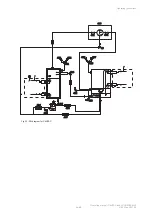
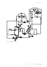
11. Charge refrigerant. The P&I diagram states the charge for each specific chiller. Start out by
charging 75% of the specified R717 charge. The quality of the refrigerant must be appropriate
for refrigeration applications; for details see: TI 2015-01 Ammonia quality.
12. Turn on power.
13. Check the UniSAB III control system settings including calibration according to the UniSAB III
manual.

