background image


Page 1 of 2


TPH/20-1-2021


Letter of compliance for ECO-design, Process & Comfort chiller 

Directive 2009/125/EC 


Manufacturer:


Johnson Controls Denmark ApS, SABROE Factory 


Christian X’s Vej 201 · 8270 Højbjerg · Denmark 
Phone +45 87 36 70 00 


We hereby declare that our products within the scope of eco-design, implemented according to regulation 
No 2015/1095 for low (-25°C) and medium (-8°C) temperatures and No 2016/2281


for high temperatures 

(+7°C), are in compliance. The harmonised standards EN 14511 series and EN 14825 have been used 
for testing and calculation. Value tolerances for selection tools comply with EN 12900.  
 
Preconditions: 
 

EER calculations are defined as COP (Coefficient Of Performance) in our nomenclature for 


evaporator calculation in COMP1 sales tools. Capacity control is variable. 

SEPR calculations are made by spreadsheet tool version 1.5.3 date 2013-09-01.  
Diagram  lines  drawn  as  straight  lines  between  legal  condition  points  and  product  points.  
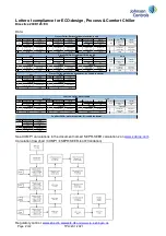
See data and calculation on page 2. Degradation coefficient Cc = 0.9 for part load. 
Specific EER, SEPR and 

η

,

SC 

values are included in the operating manual. 

Screw compressors without performance-increasing system (economizer). 

Secondary refrigerant ethylene glycol -25

°

C and -8

°

C. Secondary refrigerant water at +7°C. 

Superheat 0

°

K and subcooling approx. 1

°

K. 

Suction and discharge pressure drop included. 

Electric power for liquid pumps included according to EN 14511-3, Annex G.4. 

GWP<150 allows 10% lower value included for low – and medium temperatures. 

Chiller includes evaporator (Water/brine) and condenser (Water/brine or air). 

Examples of calculations are shown with selected models representing the respective model  


program. All other conditions or types/models must be calculated in COMP1. 


Højbjerg, Denmark 


Place 


By written authority 


Summary of Contents for ChillPAC

Page 1: ...ChillPAC and LP ChillPAC Mk 3 Chiller unit with reciprocating compressor Operating manual EN ...

Page 2: ......

Page 3: ...UniSAB III controller You can find the compressor number and the equipment configured on your unit below Chiller type ChillPAC LP ChillPAC Compressor type Designation Compressor no Refrigerant R717 Oil type PAO68 Other _____________ Level control Mechanical float valve Electronic valve Approval PED 2014 68 EU Other _____________ Supply voltage Motor 3 x _________ V _________ Hz Control 1 x _______...

Page 4: ...el data Type External surface m2 Design pressure bar Condenser Float housing Evaporator Liquid separator Oil separator Oil cooler Receiver Economiser Desuperheater Subcooler Other Pressure loss if any from safety valve to customer connection based on design pressure bar _____________ Safety valve type Back pressure dependent Back pressure independent ...

Page 5: ...ty precautions 19 2 3 1 General precautions 19 2 3 2 During operation 19 2 3 3 Cooling water systems 20 2 3 4 Cooling media 20 2 3 5 Safety during maintenance and service 20 2 3 6 Power supply 20 2 3 7 Lubricating oils 21 2 3 8 Refrigerants 21 2 3 9 Purging a refrigeration plant 21 2 3 10 F gas regulation fluorinated greenhouse gases 22 2 3 11 First aid for accidents with ammonia 24 2 3 12 Protect...

Page 6: ... 4 Vibration dampers 38 4 3 5 ChillPAC with variable speed drive VSD 39 4 4 Secondary system 39 4 4 1 General information 39 4 4 2 Cleaning in place 39 4 4 3 Temperature and flow control 39 4 4 4 Water and brine treatment 39 4 4 5 R717 detector 40 5 Operating instructions 41 5 1 General information 41 5 2 Pre start 41 5 2 1 Pre start check 41 5 3 Starting 41 5 3 1 Starting procedures 41 5 3 2 Norm...

Page 7: ...0 5 6 3 Testing of chillers 51 6 Maintenance instructions 52 6 1 Maintenance of the chiller unit 52 6 2 Selecting lubricating oil for ChillPAC units 53 6 3 R717 charge 53 7 Final disposal 54 7 1 Safety precautions 54 7 2 Waste disposal 54 8 Appendices 55 8 1 Spare parts list for HP float valve 55 8 2 Spare parts list for CVUA 1201 oil recovery pot 56 8 3 Declaration of conformity 57 8 4 Set up gui...

Page 8: ...on Johnson Controls Denmark is not liable for damage occurring during the warranty period where this is attributable to incorrect operation All compressor intervention within the warranty period must be performed by competent person nel only If not the warranty no longer applies 1 1 1 Amendments to the manual 2021 06 Version 6 Copy of declaration of conformity removed from the manual It is now onl...

Page 9: ...by Johnson Controls Denmark ApS Christian X s Vej 201 8270 Højbjerg Denmark Phone 45 87 36 70 00 CVR No 19 05 61 71 www sabroe com Copyright Johnson Controls Denmark This manual must not be copied without the written permission of Johnson Controls Denmark and the contents must not be imparted to a third party nor be used for any unauthorised purposes Contravention will be prosecuted The original v...

Page 10: ...and or minor injury Note Indicates an operating procedure practice etc or portion thereof which is essential to highlight 1 1 4 Requirements for competent persons Personnel working on the unit must be competent in accordance with national safety rules and regulations relating to flammable refrigerants or according to EN 13313 Maintenance work must be performed according to EN 378 or ISO 5149 suppo...

Page 11: ... utions initiated by the customer after delivery The secondary side on the evaporator and condenser is only intended for water or brine as cool ing medium The secondary medium is stated on the P I diagram Deviations are only permitted with a written permission from Johnson Controls Denmark Installation of the chiller in potentially explosive atmospheres must only take place if the chiller is fitte...

Page 12: ...creating acids which will destroy the pumps However check with the local authorities as exemptions to this rule may be granted Warning Johnson Controls Denmark is not liable for injuries to personnel or damage to equipment resulting from using the equipment for other purposes than the ones stated above 2 2 Identification 2 2 1 Identification of equipment All equipment from Johnson Controls Denmark...

Page 13: ... pressure Allowable pressure Category Pressure system Refrigerant charge Max Allowable temp Min Max Refrigeration unit No Type Year Fluid Group Control V Hz kg bar g bar g C LP side HP side Johnson Controls Denmark ApS Christian X s Vej 201 8270 Højbjerg Denmark www sabroe com 2516 343 Main Fig 3 Name plate for ATEX unit Установка холодильная Назначение Код стандарта сертификата Хладагент Жидкость...

Page 14: ...m The low pressure side of the unit piping system is referred to as the LP side The high pressure side of the unit piping system is referred to as the HP side Category For EC PED approval The maximum category of the piping system CAT 1 2 or 3 or of the assembly unit and piping CAT 3 or 4 Allowable pressure max The max pressure pressure relative to atmospheric pressure that the unit piping system h...

Page 15: ...frigerant Swept volume Pressure system Allowable pressure Test pressure LP side HP side No Type Year Speed bar g bar g m3 h Max rpm Fig 6 Name plate for ATEX compressor Fig 7 Name plate for compressor with EurAsian Conformity mark EAC Johnson Controls Denmark ApS Christian X s Vej 201 8270 Højbjerg Denmark www sabroe com Test pressure Allowable pressure Pressure system LP side HP side Year No Type...

Page 16: ...pt volume of the compressor at nominal speed Pressure system The low pressure side of the compressor is referred to as the LP side The high pressure side of the compressor is referred to as the HP side Allowable pressure max The max pressure pressure relative to atmospheric pressure that the compressor has been designed for in terms of pressure strength design The maximum practical operation press...

Page 17: ...arty notified body For EC PED approval CAT Category 1 2 3 or 4 according to the PED directive Side For heat exchangers only Refers to the columns Shell side and Tube side Fluid Designation of the primary refrigerant s and the secondary refrigerant s For EC PED approval Designation of the refrigerant s and or the highest fluid group Group 1 or 2 according to the PED directive Allowable pressure PS ...

Page 18: ...and units are usually delivered without refrigerant and oil To protect the compressors against internal corrosion they are delivered evacuated of all atmospheric air and charged with dry Ni trogen N2 to an overpressure of 0 5 bar 7 3 PSI In such cases a yellow sign is affixed to a visible spot on the compressor The magnetic field on the rotor may affect pacemakers The motor rotor contains a powerf...

Page 19: ...refrigerant and or lubricating oil Use proper electrical safety protection Note These instructions only provide general information The owner of the refrigeration plant is re sponsible for ensuring that all codes regulations and industry standards are complied with 2 3 2 During operation Warning All safety features disengagement and interlocks must be in place and function correctly before the equ...

Page 20: ...nd EN 13313 ISO 22712 Read chapter 2 Safety in this manual before opening the compressor and other parts of the re frigeration plant If the switch is not locked all start buttons must be tagged with DO NOT START tags and an explanation Work on unit in progress Make sure that the motor cannot start up inadvertently Switch off all electric components on the compressor unit before starting the disman...

Page 21: ... always collect the used oil in containers marked waste oil and send them to an approved hazardous waste disposal site It is not recommended to reuse oil 2 3 8 Refrigerants Be very careful when dealing with refrigerants For safe handling please refer to the safety data sheets delivered by the refrigerant supplier Warning Be aware that large amounts of leaking or released refrigerant entail a risk ...

Page 22: ...ive GWP Global Warming Potential according to the F gas regulation The so called HFOs and natural refrigerants do not fall under the scope of the regulation Refrigerant GWP Global Warming Potential R134a 1300 R407C 1650 R404A 3785 R507 3850 Requirements of the F gas regulation include Bans and limitations Labelling Leakage test Recovery of refrigerant Certification of personnel Record keeping Bans...

Page 23: ...een repaired to ensure that the repair has been effective Recovery of refrigerant Operators are responsible for putting in place arrangements for the proper recovery of fluorinated green house gases by competent personnel to ensure recycling reclamation or destruction Certification of personnel According to directive 303 2008 it is mandatory for the member states to establish certification and tra...

Page 24: ... installations with ammonia When applying first aid the persons assisting must be duly protected to avoid further injuries First aid measures Inhalation Immediately move affected personnel into fresh air and loosen clothing restricting breathing Call a doctor ambulance with oxygen equipment Keep the patient still and warmly wrapped in blankets Do not in any way attempt to provoke vomiting or to gi...

Page 25: ... attack the human nervous system When halogenated gasses come into contact with open flame or hot surfaces over approx 300 C they will decompose to produce poisonous chemicals These have a very pungent odour and will thus warn personnel of their presence In high concentrations R717 causes respiratory problems When the amount of ammonia vapour in the air is between 15 and 28 vol the combination is ...

Page 26: ...Emergency stop In case of an accident push the emergency stop button on the UniSAB III controller Fig 11 UniSAB III built into the electrical panel Fig 12 UniSAB III as a separate device For resetting and further information please see the UniSAB III manual Emergency stop Emergency stop ...

Page 27: ...ust be connected to an external condenser The ChillPAC and the LP ChillPAC only use R717 as refrigerant Once the unit is charged with R717 connected to electricity and pipe connections to water brine are established it is ready for operation The unit is provided with adjustable anti vibration machine feet for installation on a solid concrete floor For installation on decks special vibration damper...

Page 28: ...or Liquid separator 2 Condenser Oil separator 3 Expansion valve 4 Inlet evaporator 5 Outlet evaporator 6 Inlet condenser 7 Outlet condenser 8 Compressor 9 UniSAB III controller and emergency stop built into electrical panel optional 10 Motor 11 Oil recovery system from evaporator 12 Oil return system from oil separator 13 R717 charge valve 14 Electrical panel 15 High level alarm 1 15 5 4 13 11 12 ...

Page 29: ...ver 4 Inlet evaporator 5 Outlet evaporator 6 Expansion valve 7 Liquid level column and level sensor 8 Compressor 9 UniSAB III controller and emergency stop built into electrical panel optional 10 Motor 11 Oil recovery system from evaporator 12 Liquid inlet receiver 13 Equalizing receiver 14 Oil return system from oil separator 15 R717 charge valve 16 Drain valve from receiver 17 Electrical panel 1...

Page 30: ...ger where plates are welded together into cassettes R717 evaporates between the two welded plates which make up the cassettes and water brine is cooled in the channels inside the cassettes The R717 droplets are separated from the vapour in the separator room above the plates The evaporator has one or two sets of brine connections depending on size and operating conditions A sight glass is mounted ...

Page 31: ...ualising line 4 Connection for safety valves 5 Connection for manometer 6 Connection discharge pressure to oil recovery system 7 Drain including stop valve and quick closing drain valve 8 Sight glasses for liquid level check 9 Liquid plugged 10 Connection for purge valve The receiver must never be filled completely with liquid The level can always be checked in the 3 sight glasses Warning The leve...

Page 32: ...e high pressure side of the plant can equalise to the low pressure side at standstill For further information about the HP float valve see appendices Fig 16 HP float valve 3 2 7 Air purge valve If there is air in the refrigeration plant it tends to accumulate in the receiver or the condenser On ChillPAC water cooled condenser the air purge valve is fitted at the top of the HP float valve cover at ...

Page 33: ...m the level sensor and continuously adjusts the expansion valve pos 5 Fig 17 in order to control the R717 liquid level according to the settings Due to heavy boiling in the evaporator the level in the level pipe is lower than the level in the evaporator depending on the load This must be taken into consideration when setting up the UniSAB III controller To make sure that the evaporator is not over...

Page 34: ... has an integrated piston which is driven by the discharge gas The piston closes the connec tion to the evaporator during the oil recovery cycle Fig 18 System for reciprocating compressor Pos no Component 1 Compressor 2 Evaporator 3 Level float switch 4 Stop valve 5 Stop valve 6 Stop valve 7 Solenoid valve combined with filter and stop function 8 Solenoid valve combined with filter and stop functi...

Page 35: ...e adjusted in the UniSAB III controller 3 2 11 Alarm for high level in the evaporator The ChillPAC and the LP ChillPAC external condenser both have a level switch If the R717 liquid level becomes too high in the evaporator the level switch will stop the compressor This will protect the compressor against liquid hammering See subsection 6 3 R717 charge for correct charge Note The liquid level must ...

Page 36: ...tegy 4 Connect all piping The piping design must include considerations regarding function suspen sion vibrations thermal expansion and pre stress after welding in order to avoid high load on the chiller unit connections Mount all hoses and valves for compressor cooling 5 The safety valves are fitted on the unit from factory The pipe connection to the valve discharge branch must be made in accorda...

Page 37: ...essary 16 Carry out the pre start check see subsection 5 2 1 and run the compressor in 100 capacity 17 Check the liquid level in the evaporator Droplets should come out of the top of the plates The plates should not be completely covered by liquid Check that the suction superheat is between 0 5 and 3 K If higher carefully charge more R717 18 Check the R717 liquid level again Note The liquid level ...

Page 38: ...rength and be as plane as possible Always collect weight information of the chiller unit before projec ting the concrete foundation 4 3 4 Vibration dampers The compressor unit on a ChillPAC and an LP ChillPAC is placed on vibration dampers and thus isolated from the rest of the chiller unit These dampers are adjusted to the compressor and motor weight and designed for minimum 70 vertical isolation...

Page 39: ...stem is a complex task where many things must be considered for instance load variations pressure loss service maintenance corrosion and erosion fouling Note Rapid temperature variations in the secondary system can damage the chiller It is recommended to keep temperature changes below 1 K min Install a buffer tank or balancing tank to avoid great varia tions in load and temperature Avoid fluctuati...

Page 40: ... order to obtain the correct mixture it is recommended to premix secondary refrigerants glycol or brine and to check it subsequently 4 4 5 R717 detector Installation of R717 detectors in the room and in the secondary circuit of an indirect system must be in accordance with EN 378 and or local codes and rules Detectors in the secondary circuit in indirect sys tems are recommended regardless of the ...

Page 41: ...sure that all necessary documents are available including operating manuals machine card log books etc and or other documentation required according to local rules and or EN 378 Check the following before starting the chiller 1 Check that installation is performed in accordance with the recommendations 2 Turn on the power supply and the control voltage 3 Make sure that the heating element in the o...

Page 42: ...tem conditions permit the chiller to start 2 Press the start button on UniSAB III 3 Allow the compressor to start up and stabilise 4 Check the following on the chiller unit a Mechanical tightness of the external piping bolts and valves b No oil and refrigerant leaks If not satisfactory shut down the chiller and correct the problem Top bar Content area Info bar F key area ...

Page 43: ...oat valve expansion Opens automatically 426 Stop valve expansion Open 428 Liquid drain valve R717 Closed 431 Stop valve for oil drainage Open 432 Charge valve R717 Closed 433 Stop valve for oil recovery Open 436 Stop valve for oil recovery Open 437 Stop valve for oil return Open 442 Double stop valve One outlet open one outlet closed 443 Safety relief valve Closed Fixed set point 444 Safety relief...

Page 44: ...g manual ChillPAC and LP ChillPAC Mk 3 44 68 010823 en 2021 06 Operating instructions Fig 22 P I diagram for ChillPAC NO NC F F 409 TT 402 401 425 421 426 446 445 447 443 442 444 433 431 436 437 45 428 432 400 ...

Page 45: ...en 427 Stop valve for pressure gauge Open 428 Oil R717 drain stop valve Closed 429 Purge valve Closed 431 Stop valve for oil drainage Open 432 Charge valve R717 Closed 433 Stop valve for oil recovery Open 434 Stop valve for oil recovery Open 436 Stop valve for oil recovery Open 437 Stop valve for oil return Open 438 Drain valve quick closing Closed 442 Double stop valve One outlet open one outlet ...

Page 46: ...C Mk 3 46 68 010823 en 2021 06 Operating instructions Fig 23 P I diagram for LP ChillPAC M M M NO NC F 409 TT A 423 B 402 401 41 443 442 444 446 445 447 428 427 429 438 434 433 431 436 45 437 432 400 Not delivered by Johnson Controls Denmark ...

Page 47: ...ata to be checked 2 Check that oil pressure is obtained and that the evaporating and condensing pressures are with in the permissible ranges 3 Check the other operating data 4 Check for abnormal noise and vibrations 5 Check the oil and refrigerant level 6 Make sure the chiller is operating stably not fluctuating 5 4 2 Monitoring of operation To ensure satisfactory operation it is required that you...

Page 48: ...Operating manual ChillPAC and LP ChillPAC Mk 3 48 68 010823 en 2021 06 Operating instructions Fig 24 The checklist which MUST be filled in during commissioning and start up ...

Page 49: ...ate the motor and compressor weekly monthly according to below 4 If the compressor is water cooled drain of the water To reduce the risk of bearing damage it is recommended to rotate to a new position the motor and compressor on a monthly basis If the chiller unit is exposed to vibrations during a long shutdown period the position should be changed weekly Avoid high vibration level 5 6 Shutdowns a...

Page 50: ... and 3 lower power consumption Too low evaporating temperature Cause Solution Fouling in the evaporator Clean the evaporator Oil in the evaporator Inspect the oil recovery system Insufficient R717 charge Check liquid level in evaporator Charge more R717 to the plant Suction gas superheat should be approx 0 5 to 3 K A 1 K higher evaporating temperature results in a 4 higher cooling performance Miss...

Page 51: ...aporator Drop in oil temperature Cause Solution Wet suction gas due to too high R717 charge Reduce charge Wet suction gas due to unstable LP regula tion LP ChillPAC only Adjust settings for LP regulator in UniSAB III until R717 level in evaporator is steady Wet suction gas due to fluctuating load Check secondary system Wet suction gas due to quick changes in compressor capacity Adjust settings for...

Page 52: ...Daily maintenance consists of visual inspections Inspect the chiller unit and check that both noise and vibrations are normal To observe trends it is recommended to enter the observed operating data in an opera tions log see 5 4 2 Monitoring of operation Check that all operating values are within the permissible ranges Compare them with previous values to detect trends Check the oil level Check th...

Page 53: ...tages High chemical stability it is suitable for long term operation Low vapour pressure lower oil carry over from the compressor High viscosity index better oil recovery from evaporator 6 3 R717 charge It is very important that the chiller has the correct charge The P I diagram states the charge for each specific chiller At normal operation the suction superheat should be between 0 5 3 K In the e...

Page 54: ... very careful when using cutting tools such as angle grinders or flame cutters during the dismantling process as pipes and the like contain oil residue and refrigerant which may be toxic and or flammable 7 2 Waste disposal Machine parts When dismantling the plant it is important to properly sort the parts that should be disposed of The compressor frame containers and so on belonging to the categor...

Page 55: ... 8 1 Spare parts list for HP float valve Fig 25 HP float valve Pos Pcs Part no Description 1 1 1331 672 O ring 2 1 1331 126 O ring 3 040 1 1364 405 HP Float valve HFI 040 3 050 1 1364 406 HP Float valve HFI 050 3 060 1 1364 407 HP Float valve HFI 060 3 070 1 1364 408 HP Float valve HFI 070 2 1 3 ...

Page 56: ...o Description 1 3247 128 Complete pot 1 1 3445 508 Float switch 2 1 1331 433 Seal ring 3 1 3413 038 Piston 4 1 3411 009 Oil reservoir 5 1 2144 049 Spring 6 1 3411 039 Cover 7 1 1331 571 O ring 8 4 1425 018 Screw M12 x 30 9 2 1427 045 001 Threaded bar M14 10 2 1432 034 Nut M14 11 1 1344 365 Flange DN25 12 1 1336 029 Gasket DN25 NO 3247 128 3 4 5 6 7 8 11 1 2 12 NO N C 9 10 ...

Page 57: ...ion of the declaration however not filled in with the specific data for your unit The translated version is also included in the operating manual that is available for download with the rest of the order specific documentation The original signed declaration of conformity is sent separately in accordance with the Guide to applica tion of the Machinery Directive If more than one declaration of conf...

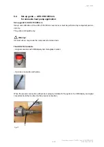
Page 58: ...vel sensor must be performed by competent person nel only The guide is in English only Warning Incorrect set up may cause the compressor to break down The AKS 4100 contains A signal converter with HMI display and meta glass solution A process connection with probe When the process connection with probe is properly installed in the system the HMI display and signal converter should be mounted on th...

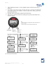
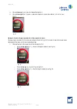
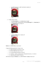
Page 59: ...HMI display is always needed Connect the device to the power supply see the section Electrical installation connection Press 3 times Press Press or to select between SINGLE COAXIAL D14 and COAXIAL D22 Choose D22 and press Press AKS 4100 QUICK SETUP YES NO AKS 4100 D22 Press to change the PROBE LENGTH Press to change the position of the cursor Press to decrease the value or to increase the value Pr...

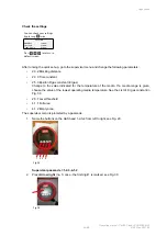
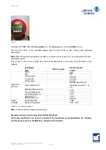
Page 60: ...tance 2 3 3 Time constant 2 5 3 Epsilon R gas constant Er gas Change to the value indicated for the temperature of the media If a media range is given choose the value of the lowest operating media temperature See the List of Er gas constant in Fig 39 2 5 7 Level threshold 4 1 1 Full area 4 1 2 Empty area The supervisor menu is protected by a passcode 1 Name the buttons on the AKS head 1 2 3 4 fro...

Page 61: ...w to change a parameter in the supervisor menu Change of gas constant 2 5 3 to value according to the list in Fig 39 If in doubt choose the lowest value belonging to the lower end of your operating range 1 Change the text in the upper line in the display to 2 5 3 Press Arrow right no 1 the second digit is marked see Fig 32 Fig 32 Press Arrow up no 4 until 1 has turned to 5 Press Arrow right no 1 t...

Page 62: ...o 3 and Arrow up no 4 see Fig 35 Fig 35 Confirm with Return no 2 see Fig 36 Fig 36 Return no 2 always takes you up one level Change the following parameters in the same way 2 3 2 Blocking distance from 50 mm to 0 mm 2 3 3 Time constant from 5 sec to 1 sec 2 5 7 Level threshold from 200 mm to 150 mm 4 1 1 Full area confirm or change to 0 mm Passcode for level 4 x x 4 3 4 2 4 1 4 1 2 Empty Area from...

Page 63: ...ogbook Installation date Filled in values Recommended values AKS 4100 280 mm Probe D22 CO2 NO Probe length 280 mm 4 mA scale 210 mm 20 mA scale 60 mm Gas constant 2 5 3 See the list in Fig 39 heat pump approx 1 2 1 4 Blocking distance 2 3 2 0 mm Time constant 2 3 3 1 sec Level threshold 2 5 7 150 Full area 4 1 1 0 mm Empty area 4 1 2 260 mm ICAD ICAD speed i04 100 UniSAB Set point regulation 20 25...

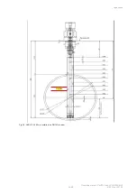
Page 64: ...Operating manual ChillPAC and LP ChillPAC Mk 3 64 68 010823 en 2021 06 Appendices Fig 38 AKS 4100 280 mm installed in a DN150 receiver Set point zone ...

Page 65: ...Operating manual ChillPAC and LP ChillPAC Mk 3 010823 en 2021 06 65 68 Appendices Extended list Gas constant for ammonia heat pump application Fig 39 ...

Page 66: ...application 12 Competent persons requirements 10 Components on a ChillPAC 28 Components on an LP ChillPAC 29 Compressor 30 Compressor name plates 15 Condenser 30 Control system 30 Cooling media 20 Cooling water systems 20 CVUA 1201 oil recovery pot 56 D Declaration of conformity 57 Detector R717 40 E Emergency stop 26 Evaporator 30 F F gas regulation 22 Final disposal 54 First aid for ammonia acci...

Page 67: ... LP ChillPAC 46 Power supply 20 Pre start check 41 Protecting the operator 25 Purging 21 R R717 charge 53 Receiver 31 Refrigerants 21 Restarting 47 S Safety during maintenance and service 20 Safety signs 18 Secondary system 39 Selecting lubricating oil 53 Shutting down 49 Sound and noise data 38 Spare parts list 55 56 Starting procedures 41 Stopping 49 T Temperature and flow control 39 U Unit pipe...

Page 68: ...Operating manual ChillPAC and LP ChillPAC Mk 3 68 68 010823 en 2021 06 Vibration dampers 38 VSD variable speed drive 39 W Water 39 ...

Page 69: ......

Page 70: ...Johnson Controls Denmark ApS Sabroe Factory Christian X s Vej 201 8270 Højbjerg Denmark Phone 45 87 36 70 00 www sabroe com Version 6 ...

Page 71: ...alculations are made by spreadsheet tool version 1 5 3 date 2013 09 01 Diagram lines drawn as straight lines between legal condition points and product points See data and calculation on page 2 Degradation coefficient Cc 0 9 for part load Specific EER SEPR and η SC values are included in the operating manual c Screw compressors without performance increasing system economizer d Secondary refrigera...

Page 72: ...tor Inlet outlet 12 7 Evaporator Inlet outlet 12 7 Evaporator Inlet outlet 12 7 2 8 12 7 2 8 12 7 Evaporator Inlet outlet Reciprocating Screw Evaporator Inlet outlet 12 7 Evaporator Inlet outlet Eta s c 12 7 Comfort Chiller water cooled 400kW 229 kW Evaporator 12 7 Conditions Eta s c Legal limit 161 400kW 324 kW 252 Eta s c Legal limit Eta s c Legal limit 1500kW 1061 kW 1500kW 927 kW 1500kW Screw ...

Reviews: