Operating manual - ChillPAC and LP ChillPAC Mk 3
32/68
010823 en 2021.06
3.2.6
HP regulating system (water-cooled condenser)
The ChillPAC (water-cooled condenser) unit is equipped with a
mechanical HP float valve.
This valve controls the expansion between the LP and HP sides of the refrigeration plant.
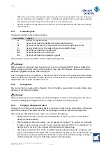
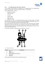
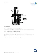
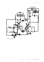
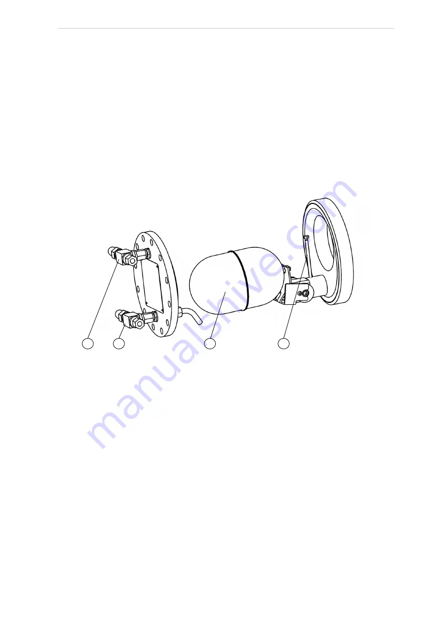
The mechanical float valve, pos. 1 in Fig. 16, is fitted in the float valve housing under the condenser in
order to obtain a compact design and a very low refrigerant charge. The float valve is fixed with a screw,
pos. 2 in Fig. 16.
The float valve is equipped with a turning mechanism which opens up two nozzles while the liquid level
rises in the condenser and float valve reservoir. The expansion nozzle will never seal tightly. This en-
sures that the pressure from the high pressure side of the plant can equalise to the low pressure side at
standstill.
For further information about the HP float valve, see appendices.
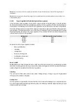
Fig. 16: HP float valve
3.2.7
Air purge valve
If there is air in the refrigeration plant, it tends to accumulate in the receiver or the condenser.
On ChillPAC (water-cooled condenser), the air purge valve is fitted at the top of the HP float valve cover
at the bottom of the condenser, Fig. 16, pos. 3.
Note:
The valve at the bottom of the cover, Fig. 16, pos. 4, is used for liquid draining (R717).
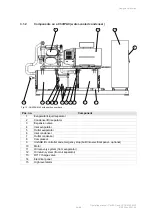
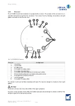
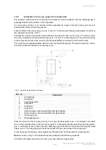
At the LP ChillPAC (external condenser), the air purge valve is fitted on the top of the receiver, Fig. 15,
pos. 10.
During air purging the air purge valve should be connected to an open vessel containing water via a re-
frigerant hose.
The air will leave the water as bubbles whereas the R717 gas will be absorbed by the water.
Note:
R717 containing water must be disposed of in a correct and proper way, see chapter
3
4
1
2

